Jay Harris is good people!! Mike Weber is the head of their tech department and is invaluable when it comes time to program the options on your system and figuring out the best way to wire "non-standard" situations.
Here are some pics of the current ISIS Power wiring install I'm doing and some notes to consider as you plan out your systems...
This is the central electronics panel that will mount in the center up under the dash with all of the fuses and relays to run the vehicle systems. I'm using 3 Powercells on this install with the third controlling interior power distribution to minimize the amount of back and forth I ended up doing on the Chevelle between the engine bay, passenger compartment, and trunk due to options that were powered up by the same circuit. Module on the left is the XFI ECU, Middle is the PowerCell, and the right is the MasterCell. The 22ga wires you see on the right side are the input wires to the MasterCell. I've gone through and de-pinned all of the inputs I didn't need to minimize the harness. They give you A LOT of input options... way more than you would ever need but it just speaks to the flexibility of this system- Stick to the "Basic Wiring Schematic" they provide with the system and it will simplify the mental processing!! The 14g wires you see coming out of the PowerCell in the center are your Output wires that you use to power up your options. Everything to the left of the PowerCell in the middle is for the EFI system. You can see that there is more wiring in the EFI than in the ISIS system. (Man, that looks ugly in the pic... I need to start running those wires out of the EFI connectors through shrinkwrap too!!) I'm OCD so I wire connectors in between different harnesses in case they need to be removed for service... thus the connectors between the XFI and the ISIS harness.. and then connectors between those and the dashboard harness.

The second pic shows the rear electronics panel for the trunk. The battery is just set in place now but they both will be sunken back into the quarter panel cavity and hidden behind trim. This panel shows the rear PowerCell, the fuel pump controller, the InReserve battery disconnect solenoid and the ISIS Maxi fuses. They were nice enough to include a 250a Maxi fuse for the battery supply cable as well. TI have also wired a secondary 4 fuse panel in the back... In reality there will be a few things that you do need to wire around the ISIS system. I run a separate keep alive circuit for the radio and the XFI system needs to be powered directly from the battery (to avoid electronic noise issues) so I fuse the wire before running it up through the car.
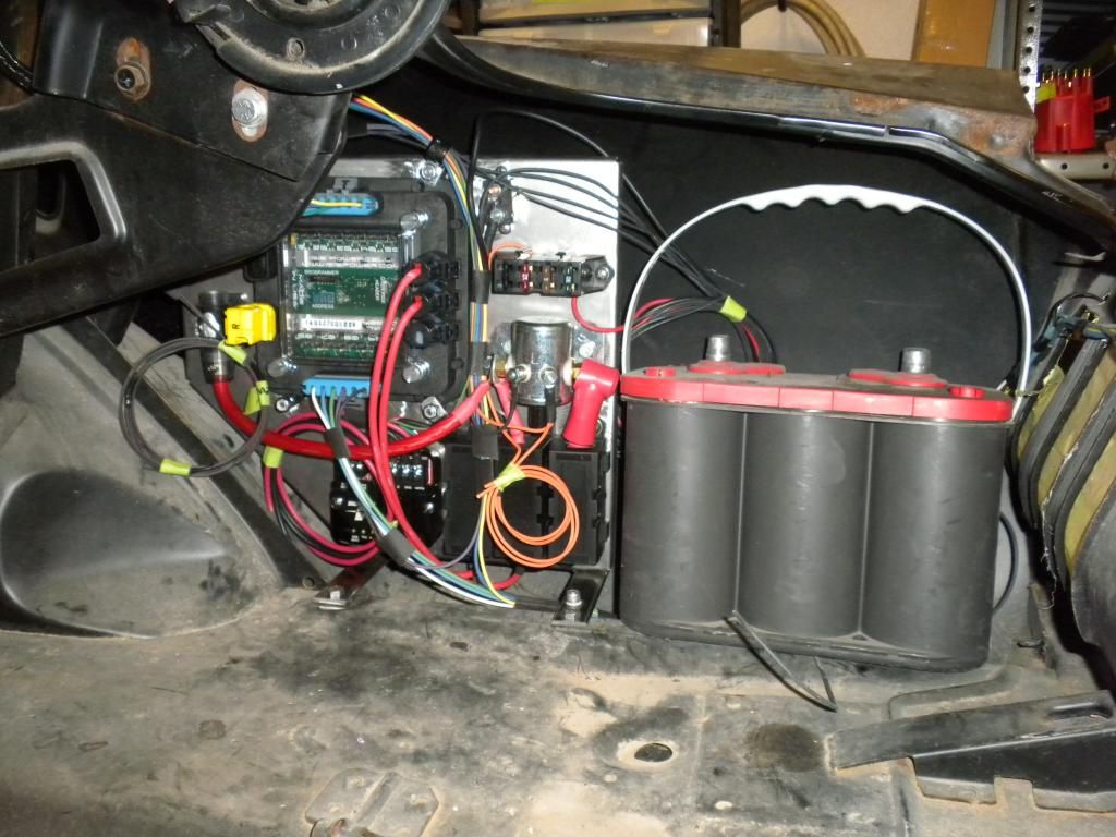
Another note to consider is that ISIS does not transmit signals... so in this case the fuel pump controller ramps up operation by tachometer signal so you do have to run a tach signal wire from your source back to wherever you have your controller... typically in the trunk. I've heard they were working on a solution for this but last I looked you still had to run wiring back from the front lighting to your indicators in the dash... (high beam, turn signals)
Working with Mike Weber comes in handy when you need to figure out work arounds for the system. I was wiring the dash lighting last week and although they provide you with a diagram for the 67-68 Mustang lighting switch it does not accomodate an instrument lighting dimmer function. We were able to work out a way with diodes to use the headlamp switch rheostat to regulate the ground but not backfeed into the rest of the ground inputs to the MasterCell.
And one more thing that will drive OCD wiring guys like me crazy and I've given Mike and Jay a hard time about this in the past but it is what it is... When they were designing the inputs on the board they didn't have the connectors finalized yet so the Input numbers to the MasterCell do not match the Pin Cavity Numbers on the connectors. The Pin Cavity numbers count left to right across the connector in two rows but the Input numbers count up and down so Input1 = Cavity A1, Input2= Cavity A17, Input3=Cavity A2, Input 4= Cavity A18, and on..
Remember that all of your inputs are grounds. Instead of supplying power to your switches you supply ground to your power circuit that your switch sends back to the MasterCell to activate your desired input. The MasterCell has a large number of 22ga grounds that you can opt to wire as your supply ground should you choose.
Heavy load items over 25a you will have to fuse and relay control your loads separately. I've discussed this with Mike on several occasions as the hardware we use on these cars tends to have 30a fusing for fans, fuel pumps, etc. That rating covers the amperage spike when these components ramp up but the operating amperage is typically within the capacity of the ISIS system. Mike has offered in the past to test components sent in to verify if the initial spike exceeds system capability... I'm not guaranteeing he does that for everyone but he has really gone out of his way to help me get my systems lined out so I'm sure if you asked nicely he would if you were really concerned about it... otherwise... just run a relay and use the ISIS system to trigger it.
Think about dedicating one of your circuits to switched B+ to activate your components. Think about a separate Accessory circuit for engine off.. waiting for someone listening to the radio or wanting to roll the window down. Think about dedicating a circuit to your Hot at All times circuits like courtesy lamps.
These systems require thinking about wiring completely differently than you have in the past. Feel free to email me or PM me if you guys have any questions.


 Brian Hobaugh SCCA National Tour June 2014
 First Hemi 'Cuda Convertible Ever Built
 Short clips: Goodguys Pleasanton autocross and pit videos


 Linear Mode

