...

Go Back   Lateral-g Forums > Lateral-G Open Discussions > Project Updates
User Name
Password


Reply
 
Thread Tools Display Modes
  #1  
Old 05-14-2018, 02:56 PM
nickcornilsen's Avatar
nickcornilsen nickcornilsen is offline
Member
 
Join Date: Oct 2011
Location: Roseburg, OR
Posts: 85
Thanks: 0
Thanked 29 Times in 16 Posts
Default 72 Nova - C5 Corvette Suspension Swap Project!

This is a relocation of my "Introduction" thread... which I'll delete when the move is complete. I also updated it a little bit, since I'm no longer 24 like I was when I started this thread! It's always kind of fun to go through the thread, as I can see how this car has been with me through so much of life... from highschool, Prom night, college... now I'm married and have a toddler!

I Joined this site due to a recommendation from Robert at Automotive Design Engineering... so far I think he made a good recommendation! This site has alot of good, technical information and real build threads.

Anyway, I'm 31 now, I work as a mechanical engineer at a company that makes castings for jet engines and such, based in Portland Oregon. I became an engineer as I've always loved working with my hands on mechanical devices, largely due to my experiences working on my nova as a teenager.

About [s]four[/s] 11 years ago, I happened across a corvette chassis/engine/transaxle drop-out on eBay... and that got the gears going in my head.

Pretty much since that day, I've been planning this project. Saving money... not to buy the parts, but to buy a house with a good sized shop. With the house found, I finished out the shop, and got ready for this project.

Anyway, I've owned this car since I was 15, in 2003, when it looked like this:


I painted it before I turned 16. Did all the body work, panel replacement, primer, and final paint. Had a professional help me mask the racing stripes. I was such a fresh faced young man for my first prom!


As high school came to an end, and college began, the poor old nova began to see neglect. I couldn't afford to drive it, so it got parked, and the motor was eventually pulled and used in a circle track car. And there it sat.

As the car sat, covered in dust... I looked at corvette chassis on eBay, thought about wheel choices, engine combos. All the while saving, saving saving. I needed a place to do this project. And eventually, the perfect piece of property came along. It had a 32x24 shop. It was also cheap, well located. minutes from work, minutes from downtown Portland, and it also had some kind of house or something, which turned out to be pretty nice as well.

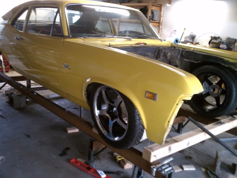
After re-wiring the house and shop, and getting my quarterly bonus and huge tax return, I was finally financially and schedule ready to begin this project. First step, dragging the old nova out of the hay barn in Roseburg Oregon up to Portland. My dad and brother get big props here for hauling the car up for me. Even after sitting all that time, it cleaned up nice!

March 2011


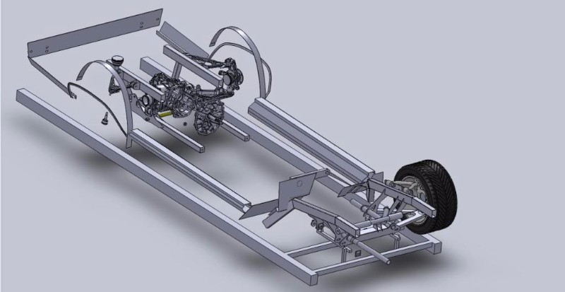
Next step: Frame jigg. This thing is square to within 1/32 of an inch, and flat to within .005" per foot. I thought having the beams right under track width of the car would be a good idea. After building it, I realized this was not the case, since I can't install a wheel and tire on the rear-end without getting them caught in the wheel well. lesson for next time is to make it a bit narrower or wider.


Last edited by nickcornilsen; 11-10-2020 at 05:04 PM.
Reply With Quote
  #2  
Old 05-14-2018, 02:58 PM
nickcornilsen's Avatar
nickcornilsen nickcornilsen is offline
Member
 
Join Date: Oct 2011
Location: Roseburg, OR
Posts: 85
Thanks: 0
Thanked 29 Times in 16 Posts
Default

April 2011

So then work began on tearing the car down. The old 9" axle and front sub frame had to go. I was able to recoup a bit of coin by selling these, which was nice.


I threw one of the 295 rear tires under the front, just for kicks.


In order to design this thing, I needed the tires and wheels, so I could figure out the track width. So i spent $1200 on tires and wheels! Aint no thang. Fronts are 265 35 17s, the rears are 315 30 18's. I also bought the corvette front and rear suspension drop-outs, and transmission.


And with that, I began the design. All CAD'd so I could have pieces cut on a water jet.
I needed to narrow the track width about 3 inches... the only steering rack that was close to the right width was from a 93-02 camaro. It is 4 inches narrower than a C5, but mounts differently.


After finishing the design, I had the parts cut out on a water-jet.


At this point, I needed to build my jig. I had all of the pieces cut out so they had a "datum" tab that was on a plane 5" above the simulated ground. i needed to build the rails for that to sit on.


Reply With Quote
  #3  
Old 05-14-2018, 02:59 PM
nickcornilsen's Avatar
nickcornilsen nickcornilsen is offline
Member
 
Join Date: Oct 2011
Location: Roseburg, OR
Posts: 85
Thanks: 0
Thanked 29 Times in 16 Posts
Default

May/June 2011

And, the assembly begins.


I spent about two hours tweaking and finessing the front cradle to be square. Doing this, you find out that factory control arms aren't perfect. Turns out the left control arm is sprung about .090 too far. I ended up getting the whole thing squared to itself within .032, and to the chassis to .032 as well.

One of the cool things about using precision water-jet cutting to make these parts is that I was able to make most of the parts self-fixturing. See the steering rack mounts below.


At this point, I started doing track-days on my SV650... this pretty much ate all of my car budget and time, so I didnt start working on it again until a few weeks ago.

By the way, does anyone from this site do car track days at Oregon Raceway? that track is amazing. very technical.

I'll post some more pics in a few.
Reply With Quote
  #4  
Old 05-14-2018, 03:01 PM
nickcornilsen's Avatar
nickcornilsen nickcornilsen is offline
Member
 
Join Date: Oct 2011
Location: Roseburg, OR
Posts: 85
Thanks: 0
Thanked 29 Times in 16 Posts
Default

Fall 2011

Now that the front suspension was installed, it was time to begin designing the rear suspension. I decided to start by laying-out the stock control arms, lacking good CAD models.

I bought a slab of granite from a counter top store. Scratch that, I bought three. I blued it up and calibrated it to a certified granit block, found it to be within .005 of flat... the other two were flat at about .020... Just an FYI for those looking fo an inexpensive super-flat surface.


I also digitized the wheel-wells of my car to check wheel fitment.


For a little bit of motivation, I threw a rear-wheel in there after i cut the wheel-wells out.


I decided I needed more accurate data about the geometry of the transmission, so I called up a locale guy who is quite well-known in the pro-touring community to use a CMM arm to measure the parts... we worked something out and I got some very good cad models. So then CAD design commenced:


Reply With Quote
  #5  
Old 05-14-2018, 03:01 PM
nickcornilsen's Avatar
nickcornilsen nickcornilsen is offline
Member
 
Join Date: Oct 2011
Location: Roseburg, OR
Posts: 85
Thanks: 0
Thanked 29 Times in 16 Posts
Default

Fall 2011

I left off on updating this thread about the time I finished designing my rear suspension... some screens shots of the cad files can be seen in my earlier posts.


After design, I went on to waterjet/laser the parts out, and began fabrication:


Gotta love a nice CNC transmission support cross member:


Next up: How to connect the engine and transmission...
Reply With Quote
  #6  
Old 05-14-2018, 03:03 PM
nickcornilsen's Avatar
nickcornilsen nickcornilsen is offline
Member
 
Join Date: Oct 2011
Location: Roseburg, OR
Posts: 85
Thanks: 0
Thanked 29 Times in 16 Posts
Default

Winter 2012 Through Fall 2014
Now I needed to figure out how to connect the engine to the transmission. The OEM solution is the 'torque tube.' there are front engine mounts, a long tube that connects from the bellhousing to the transmission, and transmission rear mounts. initially, I decided not to use this since it is large, and I was worried about interior room. Also, it is too short, and getting a longer shaft that will not vibrate is tough. So, an open shaft seemed the way to go.

Unfortunately, Nobody makes an adapter that goes straight from the clutch to a driveshaft, so I had to design my own. I make castings for a living, so I figured I'd make up a pattern and have it made from aluminum.

Aligning the engine and transmission:


Cad model of the tailhousing casting


Shaft and bearing assm design


Heck I even built it!


The problem is, it is too heavy. I drove a corvette, and it already seems like the syncros had a hard time with the rotating mass of the corvette shaft, let alone mine which is 4 times heavier! At any rate, I didn't like the solution, I was concerned the mounts wouldn't keep the engine in line, and I'd have a hard time lining everything up if I ever pulled the engine. So, I decided to go back to the torque tube.

A local shop had experience lengthing these, so they did it for me. Turns out DriveShaftShop.com can make a shaft that can handle the torque and RPM just fine, so there really is no reason not to use the torque tube. It just required some diligence in making the tunnel tight to the tube, as much as possible.


With the torque tube in hand, mounting the shifter and installing the linkage went quickly, as did installing the tunnel:


Last edited by nickcornilsen; 02-19-2024 at 04:04 PM.
Reply With Quote
  #7  
Old 06-26-2018, 09:05 AM
nickcornilsen's Avatar
nickcornilsen nickcornilsen is offline
Member
 
Join Date: Oct 2011
Location: Roseburg, OR
Posts: 85
Thanks: 0
Thanked 29 Times in 16 Posts
Default

Update time!

Since my last update, I have been focusing on the rear half of the car again.


The above photo shows me starting on the access hatch for the rear transmission. This is how I'll get to the shifter linkage to detach it for engine removal.


Sometimes you just have to get a glimpse of the end product, right?


What I leanred by moving the car up like this is that
A) A 315/30 rear tire looks disporportionate to a 265-40 front. So I have a 295/40 on the way.
B) Somehow the rear 'axle' centerline got moved forward in the chassis by 1/2". I can align my way out of that, though.
C) I don't have to raise my rear wheel well openings. I think it looks fine like this. I will raise the back by another inch though, to help even it out.


I got my order of sheetmetal! All AMD products.

Last edited by nickcornilsen; 06-26-2018 at 09:09 AM.
Reply With Quote
  #8  
Old 06-26-2018, 09:06 AM
nickcornilsen's Avatar
nickcornilsen nickcornilsen is offline
Member
 
Join Date: Oct 2011
Location: Roseburg, OR
Posts: 85
Thanks: 0
Thanked 29 Times in 16 Posts
Default


This is the trunk. To keep fumes down, I decided the fuel cell needed to be completely under the floor. The cell was mounted as low as possible, and I bought a thread-in cover with an O-Ring that goes in the trunk floor.

I didn't have the budget for an outside filler neck, so I thought this was a reasonable compromise.

At this point, I'm going to finish the floor boards and seat mounts, then do another round of primer! Then, I'll be going after the rear body sheetmetal.
Reply With Quote
  #9  
Old 06-26-2018, 12:29 PM
rustomatic rustomatic is offline
Senior Member
 
Join Date: Apr 2014
Location: ATL
Posts: 746
Thanks: 11
Thanked 57 Times in 35 Posts
Default

Great stuff, man! This is the kind of build I like to see. More of this is needed!
Reply With Quote
  #10  
Old 06-26-2018, 01:31 PM
Ketzer's Avatar
Ketzer Ketzer is offline
Lateral-g Supporting Member
 
Join Date: Feb 2008
Location: Eads, TN.
Posts: 1,408
Thanks: 303
Thanked 143 Times in 99 Posts
Default

Very cool project!

What are you shooting for on ride height? (rocker to ground in inches)


Jeff-
__________________
You remind me of the timing on a turbo engine...
Reply With Quote
Reply


Posting Rules
You may not post new threads
You may not post replies
You may not post attachments
You may not edit your posts

BB code is On
Smilies are On
[IMG] code is On
HTML code is Off

Forum Jump


All times are GMT -5. The time now is 07:06 PM.


Powered by vBulletin® Version 3.8.11
Copyright ©2000 - 2024, vBulletin Solutions Inc.
Copyright Lateral-g.net