Update time:
We got some decent weather in Houston last week, temperature had fallen but more importantly as humidity was low. I took the opportunity to burn some vacation at work i have to kill by end of the month and move towards upgrading the car's fuel system a touch.
Pump as mentioned previously had arrived.
Details:
Ricks Custom Fuel hat
Twin Walbro 525 (Hellcats)
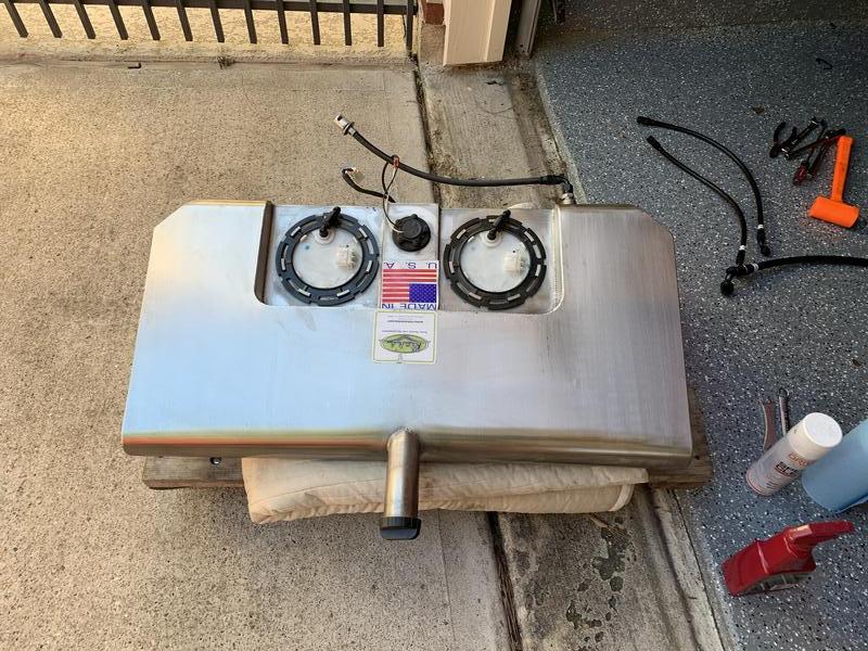
Spun aluminum fuel retention bucket.

Inside that is this: WIth the alternative that both my pumps feed through the "Primary" port on the top, as i wont have this module staged.

I proceeded to drain the 5ish, gal of fuel that was in the tank but putting my "drain hose" on the inline fuel filter, and pumped it into a spare gas can. Using holley efi and increasing pump prime time, this was pretty easy to do.
Next up was drop the tank!
I marked each location for what was primary and what was secondary pump location. This was driven off the fact i wanted to keep the "primary" as the one that feeds the flex fuel sensor, that's the only driving case, either could have been retained. Primary, as marked is the one on the right in the pic below (Driver's side of the car).

Next up was to pull both modules, one for replacement and one to replace the factory bypass valve (63-65psi) with the DeatschWerks 90psi relief valve.
Pump removed and separated from housing to access the relief valve.

Relief valve cage removed, and valve replaced.


From here that module went back in, and re-connected to the "corner pickups" that are part of the Ricks/Vaporworx system. These are EXCELLENT for corner fuel supply, sad i lose this on the secondary pump but shouldn't pose any problems.

At this point it's time to setup the second module. I loosened the screws for the spun housing and the fuel pumps and proceed to lower into the tank to ensure pump is "on bottom."

Lines installed to see what fittings i like best for the Feed (-10AN) and Return (-6AN).

Pumps wired with the pumps wired together. 8GA wire used for the pump feed as these two together as max capacity, draw significant amperage. And I always go overkill on this stuff...

Moving on from there is to mount he Fuel Pressure Regulator (FPR) that is setup as a safety bypass for the CTS-V pump. If i see a pressure spike, the hellcat pumps dont have an internal bypass, and the V bypass cant flow enough. This is a safety to ensure in that event, the V pump survives.
This looks like a good spot. By the Flex fuel sensor that the main pump feeds.

**** me, closer than i had anticipated. It would have been nicer to have a bit more room, but this is a set it and forget it type deal (i hope) so i'll suffer with the initial setup to have a clean configuration.

The lines are PTFE, so they're very still and a bit of a bear to work with.


Moving on to the feed and return lines to the tank.
As the saying goes, measure twice and cut once...Well i measured, 5 times, got "long" and "short" lengths that i felt would work for the feed and went for a mid point erring on the long side...Ended up Short....How TF.
PTFE is a mother ****er to work with as the bend radius is LARGE. I used the fittings that seemed appropriate (90deg for both -10AN and -6AN lines) and i'm not happy with either.

Shown above you can see the "ripple" in the coating as the line is short into the top of the FPR. This is unacceptable, so will be replaced. I have a 120deg fitting that I will try on the same line, prior to removing the line and checking the PTFE lining to see if it's distorted/torn/etc. I purchased additional line as well to ensure i can replace it if needed.
The return line isn't as bad, but a 120deg fitting will give a better departure for the return given it's above the rear housing to ensure no clashing will happen. i have measured and have assured myself that the shock will bottom out (bump stop) prior to contacting the line enough to cause damage to the line or the fitting. That said, that part is still pending completion, hopefully today when they all arrive.
Said **** it and went to finishing up the wiring. I'm adding a big fuse for the control of the system and the pumps, i have never been happy with the wiring to the module prior but it was "good enough." That's since changed in my philosophy and i'm trying to make it RIGHT, so at least this wont need changing when i do the car re-wire down the road.
I dont have a good photo on my PC of my old PWM fuel pump controller, but it looks like this:

Small and works to control dual CTS-V pumps, but doesn't have the thermal or amperage capacity to support the larger hellcat pumps.
Enter the new unit: This piece is significantly larger than the other, by about 3x the footprint but also about 2-3x as tall as well.


Tight squeese to get all the wiring in that box and still have room for the lid to close.

As shared previously Steve Meade Designs came through the nice ANL fuse holder. This will allow expansion in the future for not only 2 amps but potentially an onboard air system as well (if i see that as necessary).

Here it is in the trunk, where the old controller module was that has since been relocated. This position works for the sub box i have for the stereo later on down the road. Mind the dirty trunk, i wasn't in the detailing mood so it's a bit filthy.
What can be seen here is a 4Ga wire that goes to the distribution side of the fuse block, a 60 amp fuse between that and the power feed 8ga wire that goes to the controller.

Dont mind the bundle of red / white wires, that's the AC power and signal wires that will be hooked up and tidied up once the AC system is finished. They're out of the way for now.
What you can see on the right side of that screen are two wiring bulkheads. Each of these will be used as the feed for the big pumps. The red "positive" bulkhead is the PWM main power feed from the controller, and on the bottom connected to the 8GA wire to the pump itself. The black "ground" wire has multiple grounds for various sensors in the back, as well as the ground directly to the controller. There is a ground cable (2/0) that is from this directly to battery, and a 2/0 ground strap that goes to the frame now as well. Grounding has improved dramatically as part of this upgrade as well.

What is difficult to see in the photo, is directly between the battery tray and the ground bulkhead, there is a small pass through / grommet where my battery tender wire passes. Previously i had to pop the trunk to access this and it was annoying, now i can reach under car and grab the lead and connect it. I'm utilizing the former rear leave spring bushing spot to pass wires through and keep them orderly under the car.
I'll try to get some more pictures of the finished wiring under the car when i'm out there later finishing up this fuel system (lines) and setting the FPR.
To be continued!


 Brian Hobaugh SCCA National Tour June 2014
 First Hemi 'Cuda Convertible Ever Built
 Short clips: Goodguys Pleasanton autocross and pit videos


 Linear Mode

