|
|

05-17-2020, 12:57 PM
|
|
Senior Member
|
|
Join Date: Mar 2014
Location: Plano, TX
Posts: 160
Thanks: 6
Thanked 67 Times in 33 Posts
|
|

continued from above
  
Then it was a matter of wiring up the main grounding and positive cables + ECU power through this CarTek unit and then the remote button wires. It makes for a clean, reliable kill switch setup.
ECU CHOICE + MOUNTING
Another big decision people doing builds like this often struggle with is: what EFI system should I run? There are so many choices, from Holley, ECU Master, EmTron, Motec, AEM and many others. But don't count out the value leader, built with billions of dollars of engineering behind it - a GM factory ECU coupled with a stand-alone engine harness from a quality supplier (not a junkyard).

All EFI systems in any swap like this need to be tuned to your needs by a professional tuner. Not everyone has the experience or software to tune every specific aftermarket option, but virtually every tuner in the land has HP Tuners or EFI Live - which can be used to tune these factory GM "LS" ECUs. These include the 0411 (1999-02 Camaro Gen III LS 24X), E40 (LS2 24X), and E38 (LS3/LS7/later Gen IV LS) computers. There are a few others but they are odd and not as well supported. There are several ignition coil types (see below right) and several types of throttle bodies, so if you are starting with "parts" you need to know what computer can support it. The later GM computers can support both types of throttle bodies and virtually any coil type, with the right custom engine harness. The stock DBC throttle bodies are very small (75mm) but the smallest stock DBW is fairly large (90mm). I want to use a 90 to 102mm DBW TB on virtually anything, even bone stock engines.
 
You also need to have the right number of teeth on the crank reluctor (24X and 58X) to pick the right ECU. You can change reluctor wheels, but you have to pull the crank out of the block to do this right, so don't think this is trivial. The later 58X crank reluctor is better in every way (unless you have a 24X engine) and there are more choices for the DBW throttle bodies, but they do cost more. When you are doing an LS swap, however, you get to make these types of choices. This '69 Camaro started with an LS3 crate engine / LS3 sensors / LS3 DBW 90mm TB, so it was an easy choice.

The latest E38 ECU is the most powerful, cost effective, abundant, and best supported of those. And unlike all of the aftermarket EFI systems, with the right components the factory GM ECUs can be the only emissions legal options for cars that need to be "smogged". This was our first E38 build, and we tested Wiring Specialties' first E38 / 58x stand-alone harness. And we learned one thing about the E38 ECU the hard way, which I will explain later in this post.
 
The CAN network data channels from these later E40 and E38 ECUs can send loads of engine data to a digital dash and/or data logger and you have lots of tuning control - Alpha-N tuning is even possible for racier engines that are difficult to tune for driveability. We have built most of our LS swaps over the years with GM ECUs and have had no issues, and the costs for these + a harness are 1/5th to 1/10th of some of the higher end EFI systems. Only the latest Holley Terminator EFI systems can match the performance and come close to the costs of a GM E38 + harness solution.
 
After discussions with the customer we ordered a brand new E38 ECU (we often start with a used unit, but the costs have come way down on new). We already had HP Tuners VCM suite for basic tuning - but we always have an outside tuner shop do the final dyno tune + driveability programming. We can at least turn off the "VATS" security issues and get a basic tune loaded for start-up testing. We don't want to take a car to be tuned that has leaks or issues, so a start-up tune let's us do a number of tests, check cooling systems for leaks, etc.
 
Once we had the new E38, we mounted that to the tunnel, per the customer's request. This was more of a throw-back to vintage Trans Am cars that had ignition boxes and such mounted for easy access. We used these "Lord" mounts to mount to the panel, shown above right. These are rubber isolators with a threaded stud on one end and a threaded hole on the other. We mount electronics like this, such as ABS computers and surge tank/pump setups.
ENGINE WIRING HARNESS
When we chose the E38 ECU, we called Wiring Specialties to have them build the custom engine harness. This was done 2+ years ago and we got one of their first 58X reluctor LS3 style stand-along engine harnesses. We custom configured it for the coils, injectors, ECM placement and other aspects of this car.
 
I like their engine harness design as it has everything labeled, includes wired CAN flying leads, a Bussman sub-panel fusebox, is professionally wrapped, and uses new GM style connectors that plug right into this LS3 crate engine. Their tech support has also been great and we have used their LS harnesses several times.

We mounted the Bussman auxiliary panel next to the ECM and mounted the OBD-II port (which is used for programming) behind the switch panel on the center console, as shown above.
 
The engine harness worked perfectly, other than a few small changes we needed to make due to differing parts - like the alternator, which was not an OEM unit. We removed some unnecessary items as well. The harness laid into the engine bay perfectly and all of the plugs worked as designed.
 
Evan added this MAF sensor bung to the bottom of the intake tube, using a billet bung. That allows the LS3/LS7 MAF to drop in place. We don't always use a MAF sensor, especially when the engine has a BIG cam, as you can be fooled with bad sensor data from intake reversion.

Last but not least was the dual electric fan wiring, which was wired into the Wiring Specialties harness and controlled by the coolant temps on the engine via the E38 ECU.
FINISH WELDING
It was during some of the plumbing and wiring work that we had to pause, remove a few items, and finish weld them. Many of the later built brackets were still tack welded together, in case something needed to be removed, move, etc.
 
Evan spent some hours on the welding bench and bent over the chassis final TIG welding many structures before we fire up the engine for the first time.

continued below
Last edited by Fair; 05-17-2020 at 01:04 PM.
|
|
The Following 2 Users Say Thank You to Fair For This Useful Post:
|
|
05-17-2020, 01:01 PM
|
|
Senior Member
|
|
Join Date: Mar 2014
Location: Plano, TX
Posts: 160
Thanks: 6
Thanked 67 Times in 33 Posts
|
|
continued from above
PLUMBING
Lots of plumbing on this car had to be completed as the wiring was wrapping up. This is the fuel lines, which run between the lower undertray panels and the false floor in the cabin. To give the most ground clearance they were run through several frame members.
 
A flat bottom car makes for some of these difficulties, but it also gives us a cleaner install. These bulkhead connectors were installed through the frame to get from the engine bay to the fuel cell in the trunk. We ran these in aluminum hard lines, which are more robust than flex lines and cannot flop around and run into something.
 
After traversing the chassis under the passenger seat these lines go through a rear crossmember and snake up along the passenger side frame rail. They terminate into a twin bulkhead panel then flex lines run from there to the fuel cell, as shown below. This is a full return style fuel system, with a regulator in the engine bay and a full circuit to and from the fuel cell.

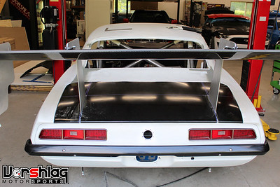
We have shown the fuel filler before, but this remote filler cap will now be hidden under the trunk, giving the car a cleaner look.
 
In the engine bay there is a fuel filter, regulator, and oiling system bits. The customer supplied the Aviad dry sump system including the 3 stage external pump, a remote oil filter, oil pan, and dry sump tank.
 
All of the AN fittings and hoses used are anodized black Fragola and their braided black hose. The oiling system was fairly complex, going from the pan to the external 3 stage dry sump pump, through an oil cooler, into the settling tank, and back to the engine plus a Peterson external vented catch can. The power steering also has its own dedicated cooler (above right) as well.
 
These TFS steam port fittings were added in place of the stock LS3 steam crossover tube assembly. This allows us to plumb the steam ports with AN fittings and proper hoses instead of a hose clamps and basic hoses.
 
You can see the coolant crossover of "steam lines" installed above, running under the throttle body to each cylinder head. The hose then goes up to the remote coolant reservoir mounted at the passenger rear of the engine bay, higher than anything else in the system. The custom built tank has an AN fitting under the cap for this circuit.
CENTER SWITCH PANEL
Please note: this center stack is temporary. We keep adding items and will redesign this after the Camaro does its first track day. We always need some dash panel to house all of the switches, within reach of the driver. Since the driver's seat is moved back considerably in this Camaro, we decided to add the switch panel to the transmission tunnel to be closer to the driver.
 
This one is fairly basic and is aimed at the driver, just past the shifter. It will house vital things like the remote kill switch and fire pull, starter button and main ignition kill. It also gets less vital switches like wipers, lights, horn, a CEL, AiM dash screen switch button, and the defroster controls. Some of these items were in flux for a while so we started with some blue tape and temporary markings.
 
I will say that I am not in love with the switch gear used here, but it isn't parts store random junk, but proper aircraft sources switches. We can and probably will update the final panel with more modern switches if the customer likes, but these work for initial track testing. The nice thing about these switches is that they mount with a simple round hole, and we can add more easily.
 
I showed this before but the open back of this panel has the OBD-II port. We keep adding things as we move through the build and this panel is getting crowded, and in the end I'd really like to have laser etched / back lit rocker switches instead.
 
We have been adding circuits and buttons as the build wraps up, even have a brake bias dial we need to mount here. Again, once we have track tested the Camaro and before paint we plan to CNC cut a new switch panel and reorganize the switches and engrave the labels.
COOLER DUCT BOX FINISH WORK
A previous entry showed the design and majority of the fabrication work involved with all of the ducting, but we still had some hours of metal work to do before this section was "finished". This is the finished assembly - which is a massive amount of fabrication, much of it hidden by the hood.

The upper ducting box will be mounted to the hood and a foam weatherstrip seal between the upper and lower boxes will be added to tie them together once the hood is closed. And while it might look like the ducting on another car you have seen, this is 100% unique setup: with a unique hood opening shape, the two coolers on the side feeding in via secondary ducting, and where the "split" happens between the upper and lower ducts.
continued below
Last edited by Fair; 05-17-2020 at 01:04 PM.
|
|
The Following 2 Users Say Thank You to Fair For This Useful Post:
|
|
05-17-2020, 01:03 PM
|
|
Senior Member
|
|
Join Date: Mar 2014
Location: Plano, TX
Posts: 160
Thanks: 6
Thanked 67 Times in 33 Posts
|
|
continued from above
 
Once we had this car in the new shop, in December 2018 Evan removed the upper duct box section, which is attached to the hood (with Clecos for now). You can see the massive hood opening needed for this big, swept back duct box. The engine's rear offset is apparent in the right picture, showing the throttle body way back behind the hood's centerline.
 
Even spent a few days welding, sanding, grinding, and hammer / dolly working this structure. I have never had anyone here that did "weld porn", and that type of pretty work isn't practical in most fabrication environments. We want structurally sound, heat consistent functional welds. This aluminum was particularly difficult to weld, for whatever reason. But Even managed to clean up all of the visible surfaces.
 
By adding weld material, then grinding / sanding it, with a bit of hammer work he made all of the upper sections look smooth and continuous. There won't need to be any bondo added to these duct boxes - which will be painted or powder coated a contrasting color against the main body's white.

This was a good view of the upper duct box after it was fitted back to the car. We bolted this in place for the track test (which I will show next time), then when it goes to paint it will be bonded to the underside of the hood. And yes, those little gaps at the back corners have been fixed - again, next time.
ECM TUNING, FIRST FIRE, AND A MYSTERY
In April of 2019 we were wired and plumbed, the E38 ECM was installed and the engine harness was plugged in and ready. It was time to fill the engine oil tank with some start up oil... it took a couple of gallons of 15W50 Mobil1, which we will use as a start-up / dyno oil before switching to a Motul oil for the track test.
 
After filling the oil tank to the level prescribed by Aviad, we removed the dry sump cog belt and spun it with a drill to prime the oiling system for the first time. We had added an external oil pressure gauge to see this vital variable during startup.

On April 18, 2019 we had the engine wired enough to crank it using the starter, but as the video above shows we were awaiting some DT plugs and connectors to wire in the rest of the ECM and fuel system.
 
In the next number of weeks Evan finished wiring in the fuel system, both oil and fuel pressure gauges now - which were still temporary. We hadn't purchased the digital dash yet, as we were still talking about that with the customer. He has a V-box data logging system he wants to incorporate from his GT3.
 
Evan loaded a basic tune into the blank E38 using our HP Tuners package. Nothing special, just a generic LS3 Camaro tune he had on hand.
 
We added 5 gallons of 93 octane fuel and bumped the starter to prime the oil system, had good oil and fuel pressure. Now it was started...

It's still open headers with no O2 sensors so it sounds pretty raspy, but we will get to that soon enough. We immediately found that while it would start and run, it would not stay running for more than a few seconds. After a a bit of testing Evan managed to get it running by adding a jumper to the fuel relay. But the ECM was not sending a steady signal to run the fuel pump. Weird? More on this below...
FRONT BRAKE UPGRADE
The brakes are super important on any track car, especially the caliper and rotors. The 69 Camaro came in with a brand of brake parts we try to avoid at all costs, so when a customer with a C6 Z06 Corvette went to go sell his car, and removed this Powerbrake 6 piston 350mm front brake system, I made sure to put him in touch with the '69 Camaro's owner. We have a lot of cars with these brakes, including several of my own cars. The brake feel, the wear, and the quality of this brand always impresses me.

We managed to get a deal going between the seller and this car's owner for these take-off Powerbrake 350x34mm rotors and 6 piston calipers / pads. We quickly installed them and they fit great - since this car uses C6 front suspension and hubs.
 
These were in great shape and had relatively new rotor rings and pads. The only worry was fit to the wheel spokes, but luckily they had plenty of room - I could stick a finger between the spoke and the caliper on the 18x11" front wheels.
 
The backing plate we made for front brake cooling was made to fit the previous caliper and rotor, but the rotor offset was the same. All it took was a little trimming to the backing plate near the caliper mounting bracket to made it fit, so we will keep the same brake cooling setup. You have no idea how much relief it gave me to get this Powerbrake system onto this car over the previous brand. Whew!
LIGHTING
Between some of the ECM work above we received a big order of Deutch connectors and Evan got to work on more of the chassis wiring - like the external lighting system.
 
This included the LED tail light kit previously installed into new replacement housings. These look period correct in every way except they are a lot brighter.
continued below

|
|
The Following 2 Users Say Thank You to Fair For This Useful Post:
|
|
05-17-2020, 01:06 PM
|
|
Senior Member
|
|
Join Date: Mar 2014
Location: Plano, TX
Posts: 160
Thanks: 6
Thanked 67 Times in 33 Posts
|
|
continued from above
 
And LED head lights: Low beam and high beam (shown above left). Cannot wait to see these lit up with the bodywork back on.
 
The chassis wiring moved forward considerably at this point with Evan wiring and bundling groups of wires to different sections of the chassis.
 
We have almost all of the lighting wrapped up and have been working on other finishing touches in recent weeks.
RUST REPAIR + BODY WELDING
 
When these cars were designed 50+ years ago they were still figuring out things like rust prevention and water drainage. The base of both A-pillars had a little rot and we stopped to fix this last bit of the chassis here.
 
Both rotten bits were cut out and replacement panels were made from new steel.
 
These were TIG welded in place then smoothed before being primed with self-etching primer. The custom cowl structure and hood hinge pockets are just ahead of these areas so now the cowl can be considered finished.

Out back the upper rear body panel just ahead of the trunk lid was just tack welded in a couple of spots, from repair work left incomplete by a previous shop. With much of the rear structure of the car cut out this panel was in danger of coming loose - so unlike a full unibody Camaro, this needed to be stitch welded.
 
Evan cleaned the primer off that Heritage had sprayed before then TIG welded the panel using a silicone bronze rod. This was done with careful application of heat to prevent warpage.
 
This was done on both sides and sanded smooth for seamless panel junction. This added some much needed rigidity to the rear of the car, which also was tied into the chassis with aluminum interior panels (see below).
continued below
|
|
The Following User Says Thank You to Fair For This Useful Post:
|
|
05-17-2020, 01:08 PM
|
|
Senior Member
|
|
Join Date: Mar 2014
Location: Plano, TX
Posts: 160
Thanks: 6
Thanked 67 Times in 33 Posts
|
|
continued from above
INTERIOR PANELS
I've shown the initial batch of interior panels in previous installments. Ryan had built the tunnel panels, flat bottom bits, and the firewall
 
When Evan took over fabrication work on this car he built the remaining panels in the same style, mounting type, and finish quality. Evan has built all of the rear panels in the interior as well as the false floor panels.
 
This trunk firewall was tied into the rear bodywork - which significantly stiffened up the body structure. We have cut so much away from this unibody that it needs to be tied into these panels to have proper structure.
 
The interior panels are wrapping up and we only have a few small details to finish in this area. I will talk about the rear wheel tubs in another post.
FALSE FLOOR PANELS
The underside of this Camaro is covered in a flat panel of aluminum, but it sits below the square tubing that makes up the tube frame. We need some panels for the driver and passenger to rest their feet on while driving, as well as to step on while climbing in over the cage.
 
There was already a short panel that was part of the Tilton pedal box on the driver's side, but we needed more there. Evan made a template from craft paper then transferred that to aluminum sheet.
 
This was being made to bolt to the tubing shown above, but there was a portion on the side that would but up against the frame rail - so he and Myles made a pair of CNC cut brackets that were bent, welded, and added to the frame. This made for a 360° frame for this floor panel.
 
The panel was then cold worked in the bead roller to give it more strength, then bolted to the frame with button head stainless hardware into rivnuts added to the perimeter mounting. Makes for a very rigid floor panel to step on when getting in.
 
The passenger side had the same basic frame shape but several fuel lines and the rear brake lines underneath. This panel was larger in shape to cover more of the brake line, so it attaches to the frame and firewall with more button head stainless hardware. We will add the bead roller lines next.
WHAT'S NEXT?
We have a lot more work to share, and I had another whole section written, but this post was getting too long so we will share more next time.
This car runs and drives now and we are wrapping up the final tasks before we do a track test, then paint. I will cover more work completed next time.
Thanks for reading!
__________________
Terry Fair @ Vorshlag Motorsports
Last edited by Fair; 05-17-2020 at 01:12 PM.
|
|
The Following 2 Users Say Thank You to Fair For This Useful Post:
|
|
05-17-2020, 07:59 PM
|
|
Lateral-g Supporting Member
|
|
Join Date: Nov 2008
Location: Dunwoody, GA
Posts: 6,298
Thanks: 664
Thanked 581 Times in 471 Posts
|
|
Thanks for the update, Terry! I'm glad to see this one is almost complete. It's so badass.
__________________
Trey
Current rides: 2000 BMW 540i/6 and 86 C10.
Former ride: 1979 Trans Am WS6: LT1/T56, Kore 3 C5/6 brakes, BMW 18in rims
|
05-19-2020, 12:08 PM
|
 |
Lateral-g Supporting Member
|
|
Join Date: Apr 2015
Posts: 588
Thanks: 981
Thanked 521 Times in 255 Posts
|
|
Soooo well done. Thanks for the behind the scenes thought process', appreciate the help, very much.
|
05-19-2020, 02:11 PM
|
 |
Lateral-g Supporting Member
|
|
Join Date: Jul 2008
Location: DALLAS, Texas
Posts: 4,544
Thanks: 296
Thanked 537 Times in 339 Posts
|
|
Love all of the detailed pics...
__________________
'68 C10 swb
'69 Camaro convertible
'72 Chevelle

|
01-04-2023, 02:45 PM
|
|
Senior Member
|
|
Join Date: Mar 2014
Location: Plano, TX
Posts: 160
Thanks: 6
Thanked 67 Times in 33 Posts
|
|
Project Update for December 1st, 2022: If you are reading this you might be thinking - was there a two year gap in updates? - and the answer is yes. We have been working on this Camaro this whole time, other than a few month or two gaps where we didn't. This was due to some staffing changes and additional customer car build projects I took on during the pandemic, which slowed down other builds.

We spent significant time in 2019 and 2020 working on this Camaro, but really hit it hard in late 2021 and 2022. Recently, after wrapping up three other customer race car builds, we were able to tackle the final punch list items on the '69 Camaro tube framed car. Now we have it running, driving, stopping and many other details completed, and it is ready for alignment and dyno, then going to the track for testing shortly after. So excited to see this one get to the finish line!
 
There's still a ton of work to cover on this Forum Build Thread on how we got there, and the images above aren't even covered in the scope of work this time. As you might imagine these write-ups consume an enormous amount of time, and I wrote this over a 4 day holiday weekend (Thanksgiving). I will skip the boring bits and get us caught up to mid 2020 in this post, but it might still take a few more updates to get us caught up to present. There are still some cool images and tech tips within, so it will be worth the read. Let's get to it!
RIDE HEIGHT CHANGES
This car came to us a rolling chassis (hot mess) with lots of parts that we ended up removing, and some big ticket items we were stuck with. Often these parts were supplied by companies that were no longer in business (the entire rear axle, the brakes, the wheels, and much more) or from companies that had radically redesigned or upgraded the parts (RideTech dampers & G-Force trans). These parts were often built in such a way that drove aspects of this build that were out of our control.

The ride height the customer wanted initially was very low and I was concerned that this was going to lead to an end result that was not well suited for track use, much less the "occasional street drives" he insisted on. With the triple disc clutch I think that any street use will never happen, but again - we didn't supply that. In late 2019 we finally had to have a talk about realistic ride heights and tire clearances.
 
The ride height we compromised on at this point was still pretty low, but we could make it work. The problem left was - to get any steering angle with the wheels & tires plus the control arms and spindles provided, it made for some unacceptable fender interference on the front tires. Just pushing the car around the shop with steering angle had caused some tire rub and small tweaks to the front fender lips. This just wasn't going to work.

We had to have another call with the customer - we either raise ride height further and/or we trim the front fenders.
 
The ride height stayed so the unobtanium aluminum front fenders were marked and trimmed at the blue line shown above. That gained us enough clearance to turn the wheel, but we would later have to re-work the front flare extensions to make that fit (also shop time I ate).
WATTS LINK CHANGES + AXLES INSTALLED
The Watts Link was another series of parts that came with this car and changing them significantly was going to involve a lot of push back. At the more realistic ride height the car was at now in late 2019, it was time to look at the geometry of the lateral arms on the Watts... the arms were too angled off of level at ride height, the "towers" these arms mounted to were too short, and not well supported.
 
A few updates to the Watts Link system were needed, which was only ever partially completed and tack welded together. The Watts Link lateral arm vertical "towers" were lengthened, with engineer Myles designing and CNC cutting these on the plasma table. Then fabricator Evan bent and welded these up, along with several gussets.
 
The towers were now longer and needed some real lateral triangulation and bracing. We came up with a 1.5" diameter main lateral brace that was curved up to clear the exhaust, that was then welded between the frame rails.
 
Jason and I worked with Myles and Evan and we came up with some triangular bracing from 1" tubing that was again curved around the dual 3" exhaust. These tied the vertical Watts Link towers to the lateral 1.75" tube between the frame rails.
 
Once this was tack welded, mocked up and signed off on from engineering, Evan stitch welded all of the braces and towers with the TIG. Lots of overhead welding fun. A couple of fuel lines had to be moved to make all of this fit and a bulkhead brace was added to hold those and brace up the curved ends of the lateral tube (see above right).

Finally my eyeball didn't twitch when I looked at all of the arms and visualized all of the load paths. This looked like it would be road and track worthy now, so it was time to wrap up some final details on the axle and rear swaybar.
 
This Ford 9" housing was supplied by a long dead company, but we needed to pull it apart to measure for axle shafts. The aluminum Moser center section and WaveTrac diff were supplied by us earlier, now it was time to finish off the floating axles. Jason drew up what we needed and we got those from Moser a few weeks later - in late October 2019.
continued below
|
|
The Following User Says Thank You to Fair For This Useful Post:
|
|
01-04-2023, 02:49 PM
|
|
Senior Member
|
|
Join Date: Mar 2014
Location: Plano, TX
Posts: 160
Thanks: 6
Thanked 67 Times in 33 Posts
|
|
continued from above
 
Evan assembled the rear end with the new axles and then the completed rear assembly went back into the car, along with the rear swaybar also supplied by some unknown company years before.
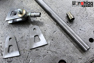 
The last thing in this rear section that needed to be completed was the swaybar endlinks - we had none, so some ends were ordered, tubing acquired, and some mounting tabs CNC cut. Those were then used to anchor the upper mount at the frame and the endlinks were welded together and rod ends assembled and that was another thing checked off the punch list.
ALUMINUM REAR INNER WHEEL TUBS
This chassis was scratch built so there were no inner tubs - these were started by a previous fabricator but never finished. It was time to wrap those up.
 
This pile of inner wheel tub parts was all we had, but the outer mating sections needed to be built and attached to the outer fenders. These would separate the cabin from the outside and keep the passengers away from flying pebbles, tire debris and rain spray.
 
These floating nut plates were added to the seams where the pieces would bolt together, to allow for a slight misalignment and shift, with small button head bolts holding it all together.
 
Cut-outs were made for some things like the rear upper endlink mount, mounting bolts to the chassis, and clearance for the axle itself. Another fabricator would tackle the mounting edge at the outer sheet metal skin of the rear fenders, as well as some other final at a later time. This had the rear tubs about 90% complete.
BRAKE LINE PLUMBING
This is one of my least favorite jobs on a "scratch built" car - making all new hydraulic brake lines for all 4 corners. There wasn't a single piece of the factory lines we could use, so this was a decent chunk of work to plumb up. This work began in late December of 2019.
 
We use a copper/nickel alloy hard tubing, which flares nicely. We use a tubing straightener we built to take the coils of hard tubing and make it straight, then use a number of tubing benders to get the line where we want to go. We often use TIG welding tire to mock up complicated sections, then transfer to the hard lines.

There is some science and some art that goes into the layout. On a normal chassis you have the frame and/or unlevel floors to route the hard lines from front to back under the car - but protected. On a "flat bottom" car like this, we like to run the lines from front to back inside the car - so an off track incident doesn't scrape the brake lines right off.
 
Luckily we have some routing between the "flat bottom" panels and the "false floor" feet panels above - just had to make a somewhat long bulkhead fitting at this lateral cross floor tube, shown above. Drilled the hole, routed the fitting through that, and made lines terminate before and after that - and again at another lateral crossmember tube behind the passenger seat.
 
I recommended a proper 4 channel ABS system on this car, but the customer wants this car to be very analog - no Anti Lock Brakes - so a 3 channel hydraulic system is all we ran. Hence the single line from front to back.
 
Once the hard line ended at the rear axle area, three flex lines were made to connect from the chassis to the middle of the axle. Then hard lines ran from a "T" out to the two rear calipers.
continued below
|
|
The Following User Says Thank You to Fair For This Useful Post:
|
|
| Thread Tools |
|
|
| Display Modes |
 Linear Mode Linear Mode
|
 Posting Rules
|
You may not post new threads
You may not post replies
You may not post attachments
You may not edit your posts
HTML code is Off
|
|
|
All times are GMT -5. The time now is 07:18 PM.
|


 Brian Hobaugh SCCA National Tour June 2014
 First Hemi 'Cuda Convertible Ever Built
 Short clips: Goodguys Pleasanton autocross and pit videos


