|
|

11-11-2018, 12:22 PM
|
 |
Moderator
|
|
Join Date: Sep 2005
Location: NorCal
Posts: 9,145
Thanks: 58
Thanked 158 Times in 104 Posts
|
|
So how much did this sell for Terry? 
__________________
2004 NASA AIX Mustang LS2 #14
1964 Lincoln Continental
2014 4 tap Keezer
|
03-04-2019, 03:54 PM
|
|
Senior Member
|
|
Join Date: Mar 2014
Location: Plano, TX
Posts: 160
Thanks: 6
Thanked 67 Times in 33 Posts
|
|
 Finally some 2018 progress to this thread!
Project Update for March 4th, 2019: Wow, what happened to 2018? It has been over a year since the last update to this project build thread, as well as many others. For me 2018 was pretty jammed up, with much of my time spent dealing with real estate issues (extending our lease, fighting a builder behind schedule on our new building construction, our shop move, our continued construction once moved in) and some staffing changes. Now that we are moved in and caught up on more important business paperwork, I have been making time on the weekends getting into the fun build coverage on some projects, like the big steps shown this time on the 1969 Camaro.

In this round we show some 2018 work completed like the rear diffuser, flat bottom undertray panels, rear wing installation, some final welding and assembly, and more. Let's get started!
UNDERTRAY WRAPPED UP
The undertray is made up of a lot of pieces that are either bonded and riveted in place or bolted in place, depending on their location and the need to access things above them. I'll zip through a few steps here quickly.

Obviously you will want to be able to access the dry sump oil pan quickly (above), so that undertray panel is removable. But these two main floor panels (below) don't have anything hidden above them that needs to be accessed quickly - just the seat and interior, which are accessible from above.

The plan was to bond then rivet these in place, so these need a LOT of hours of measuring, marking, center punching, drilling, and riveting. Since counter-sunk rivet heads would be used, to allow for a flush bottom face, every one of these rivet holes had to be countser-sunk as well.
 
Once all of the hundreds of tiny holes were drilled through the panels and into the chassis, the square tubing that these floors mount to was then prepped. These portions would not be visible again once the panels were bonded in place, so they needed to be protected from corrosion. A bit of work with some Scotch-Brite pads, some wax-and-grease remover clean-up, a bit of masking with paper and tape, then these tubes were painted with self-etching primer.
 
Now the aluminum panels themselves needed some prep work. Ryan taped off some areas then scuffed up the top surfaces of the sections to be bonded to the square tubing. This is to give those surfaces some "bite" for the epoxy to bond to. Some 2-part structural metal epoxy was applied with a mixing nozzle and the panels were ready to put in place. Ryan used an epoxy that he had used building Prototypes, which also use a bonded floor. The cross hatch pattern was one that he learned from building those cars as well.

There were some extra hands needed to get each panel in place while the epoxy was wet, and a few Clecos to hold it in place, then Ryan spent some time with the air riveter. The "spent" mandrels from hundreds of blind rivets littered the shop floor.

This picture above shows up close what the bonded and riveted center panels look like when completed. You can see the "doubler" panels that are attached to the floor panels, which secure the removable center panel underneath the driveshaft and exhaust.
REAR SECTION OF EXHAUST FINISHED
In a previous update I showed the progress on the exhaust, from the headers, through the center tunnel, the crossover and X-merge, then two MagnaFlow mufflers mounted behind the driver, just in front of the rear axle. Everything was tacked welded together, and that's where where we were before this round of work.

At the time we didn't have the rear diffuser section planned to know where the rearmost section needed to terminate. We were nearing time for the rear diffuser so the rest of the dual 3" exhaust had to be built.
 
I wanted additional 3" V-bands behind the mufflers, to make final adjustment easier and disassembly less of a chore. There are a lot of bends and turns tucked inside this tunnel. We all met and decided that a twin outlet in the front of the diffuser would be best, with one going to each side. Ryan built the final sections to aim at those spots.

These were left long, as the next step was the rear diffuser construction. Then, the two exhaust ends could be terminated at the plane of the diffuser.
continued below

|
03-04-2019, 03:55 PM
|
|
Senior Member
|
|
Join Date: Mar 2014
Location: Plano, TX
Posts: 160
Thanks: 6
Thanked 67 Times in 33 Posts
|
|
continued from above
REAR DIFFUSER CONSTRUCTION
The rear diffuser work needed to happen with the car loaded onto the 4-post lift, which was a little tricky since the under-panels were still held on temporarily with dozens of Cleco fasteners.

With the car on the lift the diffuser plane was laid out with string.
 
Jason gave Ryan the angle of the plane he wanted to see and that was laid out to fit the constraints of the chassis, solid axle, and rear fuel cell. A "test piece" was secured in place to check for length and vertical strake placement was planned.
 
Due to space constraints of the fuel cell mounting, and styling concerns from the owner, we didn't do a ridiculous rear diffuser box like we have done on other cars. What we had planned was subtle, appropriate for the rest of the aero on the car, and still effective. Ryan built these sheet steel angled mounts onto the bottom of the fuel cell mounting cage (above right).
 
Ryan built this in a relatively short amount of time, using some flat plate and bent aluminum sheet. It rivets and bolts together, which makes repairs easier if anything ever gets damaged.

This is by far the most subtle rear diffuser we have ever built. But it merges with the flat bottom under-panels and leaves very little opening under the car (just for the tires). The full flat bottom undertray forward will make this diffuser much more effective than just sticking a diffuser under a car with a "wide open" underside.
 
The final portion of the exhaust system was modified after the diffuser was in place, to better locate the exit for the volume of exhaust flow from the engine. The "tips" were flush cut at an angle that matched the diffuser plane - all we have left now is to mark that on the diffuser plane and cut the holes.
CUSTOM TRUNK HINGES
With most of the unibody "skeletonized and skinned", there wasn't any of the original mounting structure left in the rear to mount stock trunk hinges. It was time to come up with a lighter, more elegant solution.
 
Ryan built these flanges that mount to a piece of formed aluminum sheet, which will attach to the outer sheet metal skin inside the hidden flanges. The hardware that will attach these hinge assemblies to the outer steel skin will be hidden under the trunk lid and rear window Lexan.
 
With the flanges and mount built, a piece of aluminum bar was machined to fit between them, then drilled for a pin. Next up he began welding up the swing arm that will mount to the trunk lid. He used a section of aluminum bar and bent it to shape, then welded it to the piece of bar shown above that fit between the flanges. And he added a mounting flange for the underside of the aluminum trunk lid.

This is the swing arm assembly and mounting flange, which will be mounted to the bottom side of the aluminum replica 69 Camaro trunk lid.
continued below
|
03-04-2019, 03:56 PM
|
|
Senior Member
|
|
Join Date: Mar 2014
Location: Plano, TX
Posts: 160
Thanks: 6
Thanked 67 Times in 33 Posts
|
|
continued from above
 
The final assembly looks simple, but it works with precision and the fit of the trunk is perfect. The simplest solutions sometimes take a considerable bit of planning, time, and talent to pull off - Ryan made this step look easy. Now it was time to mount a rear wing - with a pair of chassis-mount uprights that pass through the trunk.
REAR WING MOUNTING
While the diffuser will generate some downforce, the rear wing we had in mind would be more effective for keeping the rear stuck down while cornering at speed. Since we made a dual splitter element up front the rear wing was going to be a modern departure from a typical 69 Camaro - a swan neck/top mounted, 14" chord, 72" wide carbon fiber Fulcrum wing made by AJ Hartman Aero. We've used this wing many times and it WORKS. It is also the one with biggest chord on the market.

I'm skipping some steps here but mock-ups of the wing element were made in Photoshop, then the element ordered, height and rear setback placements were tested, and the design was approved by customer. That all took months of back and forth, ordering, shipping, etc. Once the wing element was here Ryan made templates then started on the final aluminum uprights.
 
Ryan built uprights by hand using 6061-T6 aluminum plate (this was before we moved and got the new CNC plasma table - which is how we make them now). It takes time and precision to pull this off for a perfect matching pair of hand built uprights that look like they were made by a robot.
 
Flanges for the lower mounting of the aluminum uprights were added to the frame, the uprights were bolted in place, and the wing element was mocked up to get various Angle of Attack bolt hole layouts on the uprights. These were marked, drilled, and the wing mounted and test fit.

Not a bad looking setup, and yes, that wing is in the stratosphere. Now let's get some endplates on that wing...
 
AJ Hartman makes some really large, reinforced carbon endplates now, but at the time he didn't. So we made these big boys out of aluminum sheet, with a reinforcing bend at the back (which will likely get cut down). We started with cardboard mock-ups first.
 
Once these were cut and formed, drilled and mounted, it was time for one more little feature. This swing-up panel on the right side was added, with a simple hinge...

This allows for the optional Gurney flap that AJ Hartman Aero makes for their wings to be added. The wing was ordered with the slot molded in for the removable flap, which can be quickly removed by flipping up this little access panel on the right side endplate and sliding it out. Pretty slick.
 
The next step is to cut slots into the trunk lid for the frame mounted wing uprights. I will show that in a future installment to this thread. For now, the trunk was removed, then later the wing, so that nobody walked into those massive endplates while walking around the shop.
continued below
|
03-04-2019, 03:57 PM
|
|
Senior Member
|
|
Join Date: Mar 2014
Location: Plano, TX
Posts: 160
Thanks: 6
Thanked 67 Times in 33 Posts
|
|
continued from above
FINAL WELDING AND ASSEMBLY STEPS
There comes a point in any build when you need to stop, pull some things apart, tackle some final welding, and bond some panels on, before you get too far ahead and cover things up. We had reached that spot here - it was time to finish a few aspects before the car could be put together for the last time, at least before the dyno tune and track test...

Many removable panels were removed, the headers and exhaust were dropped down, the drivetrain came out, and access was gained to finish off parts of the firewall.
 
There were some tubes that needed to be primed and painted before some permanent panels were bonded and riveted in place, like these at the firewall and around the dry sump tank.

This upper portion of the firewall could be bonded and final installed now that the tubes were primed and ready.
 
Lots of tack welds were turned into final TIG welds on the chassis (above left) and on the custom exhaust headers (above right).

The exhaust was now fully completed front to back, so it could be final welded as well. This was done in stages, to prevent warping or movement.
 
With the drivetrain out, the trans was removed, as was the bellhousing. We didn't spec any of these parts and with what we had seen elsewhere we wanted to double check everything. The clutch was taken apart, engagement of the hydraulic TOB was verified and shimmed, the starter was checked - everything.
 
The drivetrain was reinstalled and some final welding at the custom firewall was looked at. If you remember this car came to us with some unusual and unfinished firewall work that had to all be cut away. This work allowed us to move the drivetrain back relative to the stock firewall, yet still fit headers and other things around it - which the previous builder neglected to look at.
 
With the short pieces of formed sheet metal firewall Ryan had added between the tubular structure and the stock cowl piece, it was time to weld them together then blend the seam. Lots of welding and grinding here.

The tack welded portions from before were all now final welded and primed. Some time was spent making this visible section smooth and ready for paint. The pockets here were added for the hood hinges, shown in this build thread previously. These were seam welded and smoothed also.
continued below
|
03-04-2019, 03:58 PM
|
|
Senior Member
|
|
Join Date: Mar 2014
Location: Plano, TX
Posts: 160
Thanks: 6
Thanked 67 Times in 33 Posts
|
|
continued from above
THROTTLE PEDAL ADDED
For a while we had been discussing EFI options with the customer. We weren't sure if he would go with a Motec/Emtron/similar aftermarket "Motorsports" grade EFI, which can have unique capabilities like launch control, traction control, power-by-gear, etc. The other option was a less costly and less complex GM based LS3 computer, harness, and sensor package. He made a choice - keep it simple - so we started rounding up the OEM LS3 based bits plus a custom engine harness. It makes sense, since this is just a 480 hp crate motor LS3. That decision allowed us to pick which throttle pedal to use for the drive-by-wire LS3 throttle...

We had added bottom mount Tilton pedals for the clutch and brake already, so we "borrowed" one of the pedal covers and picked up an LS3 DBY throttle pedal sensor.
 
Ryan made an aluminum bracket to mount the sensor and a pedal arm assembly, to get the height of the gas pedal to match the Tilton brake and clutch pedals. Then we ordered another matching pedal cover from Tilton to use on this 3rd pedal location.
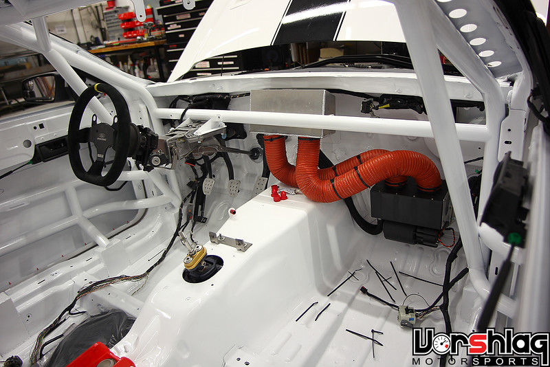
MOTORSPORTS HEATER/DEFROSTER ADDED
Even here in Texas, we have some race dates that can be cold and nasty. Our NASA season opener is usually the last weekend in January, plus our March NASA dates can be cold and foggy, at least in the mornings. I've been fogged in at more than a few events.
 Jamie Beck's S197 Mustang ST3 classed race car, which we built in 2013
One invaluable tool to combat the fogging of your windshield is a lightweight defroster box like this. We have been adding these to every race car we build for the past 6 years, and they really work. The Mustang above we built for Jamie Beck back in 2013 got one of these and it has saved him from "driving blind" on track, on more than few occasions.
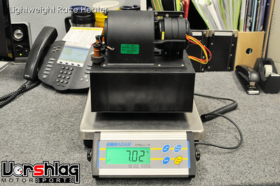 
We use this Summit Racing heater assembly that weighs a whopping 7 pounds. It has a heater core, 3 fans speeds, can flow up to 260 CFM, and will put out as much as 28,000 BTUs of heat. This compares nicely to the nearly 21 pound heater box in a late model Mustang, shown above. The Summit unit is a lot more compact and easier to mount, too.

I've shown a little bit of the install of this defroster on the 69 Camaro before, but I'm sharing the link to the part, weights, and final install this time. This was fairly straightforward. Ryan built a little sheet metal box to mount the heater box assembly right onto the tunnel, under the dash, which I showed before.
 
The twin 3" diameter outlets for warm air mate up perfectly to 3" high temp brake duct hose, which we can then direct to vents at the base of the windshield. Ryan made two aluminum defroster vent "boxes" that have a 3" round hose end for the feed and mate up to the under long oval openings on the factory metal dash (see below left). These will mount with two small button head bolts from above, but are held in place by Clecos here.
 
Above left is the view from above, down into the factory defrost vent openings. The above right picture is the view from the driver's compartment with the fiberglass dash face removed.

Two heater hoses were later added with bulkhead connectors to feed the inlet and outlet of this heater core from the water pump, as seen here. I will cover a lot of plumbing work in the next update
continued below
|
03-04-2019, 03:58 PM
|
|
Senior Member
|
|
Join Date: Mar 2014
Location: Plano, TX
Posts: 160
Thanks: 6
Thanked 67 Times in 33 Posts
|
|
continued from above
FUEL FILL AT TRUNK FACE
The fuel filler location was something we discussed with our client at length, with a balance trying to be struck between period correct, safety, and utility. We looked at ideas of a flush mount motorcycle style cap, modern pro racing quick disconnect fill openings, and throw-back AC Cobra flip up caps.
 
After we selected a filler cap and flange that matched the opening on the fuel cell, Ryan built this welded and bent aluminum mounting bracket. This was to be mounted inside the trunk and just below the surface of the trunk - which itself already needed two big slots cut into it for the wing uprights to pass through.
 
With the mounting bracket attached to the trunk at the flange and below, the filler tube could be made from stainless exhaust tubing mandrel bends. The tubing was opened up at the "neck" and the S-shaped tubing was then final welded. There is a flexible section of hose right at the fuel cell, to allow for any misalignment.
 
This is what we ended up with, which will have a mating opening in the trunk with a small "well" there to catch any spilled fuel. This way the car can be fueled with the trunk closed and wing in place - just reach back, unscrew the filler cap, and pour in from a fuel jug and hose or at the track-side pumps. I think the balance we struck fits this build the best.
WHAT'S NEXT?
This post is getting a bit long, but we covered a lot of the 2018 work. I didn't get to the rear wheel tubs and the final interior panels - we will cover that next time.
 
There is also all of plumbing work and chassis wiring to cover, most of which was completed by Ryan before our shop move in June 2018.
 
The engine harness we ordered in 2018 arrived late that year, and earlier in 2019 our new technician Evan started wiring that up and mounted the E38 GM ECU. He also tackled the final rust repair fab work on the original chassis (two spots the size of a playing card at the base of the A-pillar), filled, smoothed and finished the fab work on the various radiator and hood duct boxes, built the the remaining door bars from the roll cage, and more. It is almost ready to fire up the engine for the first time as I write this.
Thanks for reading!
__________________
Terry Fair @ Vorshlag Motorsports
|
|
The Following 10 Users Say Thank You to Fair For This Useful Post:
|
|
03-05-2019, 06:23 AM
|
|
Senior Member
|
|
Join Date: Feb 2012
Location: Behind the wheel in KCMO
Posts: 362
Thanks: 118
Thanked 40 Times in 37 Posts
|
|
Wow Terry, now THAT's a massive update! Glad to hear things are still trucking along for you guys.
__________________
I build my own junk...
|
03-05-2019, 06:47 PM
|
|
Senior Member
|
|
Join Date: Apr 2014
Location: ATL
Posts: 746
Thanks: 11
Thanked 57 Times in 35 Posts
|
|
Thanks for updating this! We don't get to see many builds like this on forums anymore, so it's a nice catch when something new comes along, especially that which relates to nearing build completion, as opposed to another drifting off into the ether.
It's not something discussed much, but one might guess that the main fabricator on this project, especially with others going on, gets creatively exhausted. Having a cohesive shop team must definitely help . . .
|
03-06-2019, 08:16 AM
|
|
Senior Member
|
|
Join Date: Feb 2005
Location: Dallas TX
Posts: 626
Thanks: 68
Thanked 170 Times in 125 Posts
|
|
Quote:
Originally Posted by rustomatic

Thanks for updating this! We don't get to see many builds like this on forums anymore, so it's a nice catch when something new comes along, especially that which relates to nearing build completion, as opposed to another drifting off into the ether.
It's not something discussed much, but one might guess that the main fabricator on this project, especially with others going on, gets creatively exhausted. Having a cohesive shop team must definitely help . . .
|
x2. it's great to see a build through until the final product. A lot of good info to be absorbed & considered.
|
 Posting Rules
|
You may not post new threads
You may not post replies
You may not post attachments
You may not edit your posts
HTML code is Off
|
|
|
All times are GMT -5. The time now is 03:43 PM.
|


 Brian Hobaugh SCCA National Tour June 2014
 First Hemi 'Cuda Convertible Ever Built
 Short clips: Goodguys Pleasanton autocross and pit videos


 Linear Mode
