Upgrading Charger Suspension With QA1
In the 1960’s muscle cars were all about going fast in a straight line. These cars had massive engines and ran like a bat out of a hell in a straight line but taking a turn at speed resulted in tires screaming for their life.
Even though in the Dukes of Hazzard series the ’69 Charger was portrayed as a stout do-it-all car, the suspension was weak and had horrible geometry from the factory. Jumping across the river surely ruined more than one ’69 Charger in the shows series. Luckily just like their GM and Ford counterparts, bolting on new suspension can drastically improve the strength and geometry of these Mopar’s.
Last year we were cruising in our General Lee replica and enjoying the hell out of it. We noticed a ton of understeer and how the car floated across the road. Even cruising to get some ice cream the handling sucked. Unfortunately a driver crashed into the car, resulting in need for new suspension. At this point we decided to ditch the factory suspension and upgrade to something that will help make this ol’ Charger handle like a Viper. Enter the suspension experts QA1.
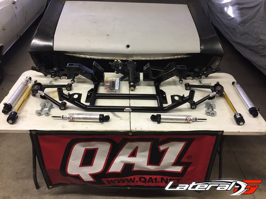
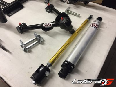
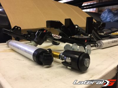
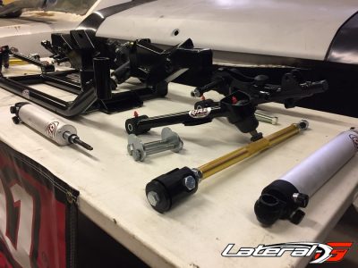
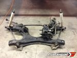
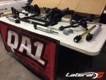
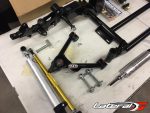
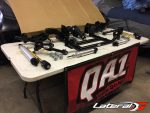
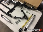
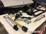
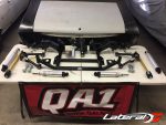
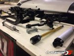
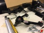
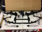
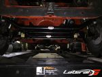
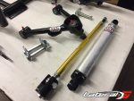
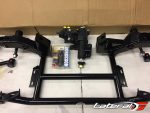
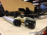
We plan on tossing the original front suspension on a 1969 Dodge Charger General Lee replica and replace it with a complete setup from QA1. Their full suspension kits are complete tubular upper and lower control arms, double adjustable shocks, adjustable strut rods, camber bolts, anti roll bar, and K member. The combination of these parts will bring the handling of our Charger into the 21st century. To compliment the suspension we will also be installing a Borgeson steering box to modernize the steering ability of this B body Mopar which is severely lacking in stock form.
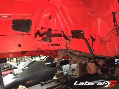
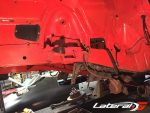
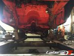
At this point, the drivetrain is already out of the car which will make the remove and replace process much easier as the K member serves as the engine cradle on these unibody cars. However you can still do this upgrade without actually removing the drivetrain.
Removal: Out With The Old
The first step is to raise the vehicle and support it on the frame rails with jack stands behind where the K member bolts to the body and remove the front tires. This is a fairly involved job, and if you aren’t familiar with mechanics we’d suggest hiring somebody to do it for you.
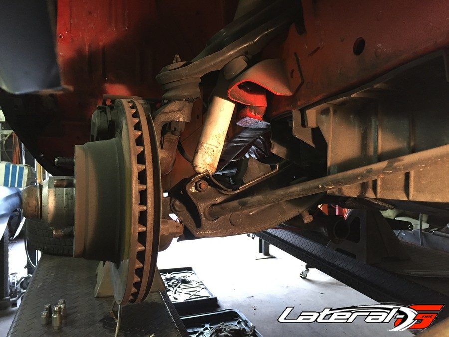
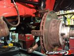
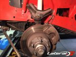
Next, we need to unload the suspension. Since these cars are torsion bar sprung, the tension needs to be relieved before going any further. But before that, we like to knock the ball joints loose to make removing the spindle assemblies easier. Remove the ball joint cotter pins and back the castle nut off about a half inch, give the ball joint area a smack with a hammer to release them. If the hammer doesn’t do the job, you can grab a ball joint separator fork and use that. Another good thing to do while under in this area is remove the plastic shields that are bolted to the frame rails so they do not get damaged while disassembling the suspension.
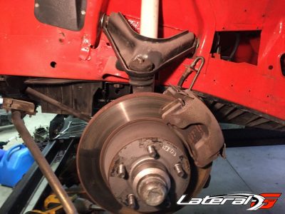
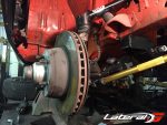
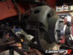
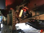
Also, if you do not want to disturb the brake system during this swap, you can remove the caliper and suspend it with a bungee cord. You never want to have any kind of weight hanging on a brake hose. Our Charger already has a disc brake conversion on it using late model Chrysler slider type calipers.
Now, there is an adjuster bolt on each lower control arm to release the spring load of the bars. Since we are not reusing the adjusters or lower control arms, we used an impact wrench with a ¾” socket to unload them. Once the spring load is off, remove the retainer clip that keeps the torsion bar held in place. This can be found on the back side of the bar where it slides through the frame. A pair of pliers will get the job done. Removing the bars themselves can be a little tricky depending on how long they have been installed in the car. The old trick is to use 2 vice grip pliers clamped around the bar butted up against each other. A few swings of a hammer should knock them loose and out of the chassis. Don’t forget to pull the rubber dust boot off the front of the bar. Very important to keep the torsion bars marked which side and way they came out of the chassis. They are right and left specific.
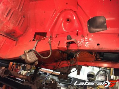
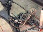
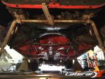
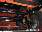
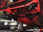
Once the torsion bars are out of the way, there are several ways to disassemble the front end of a Charger. The entire front suspension can be removed as one assembly simply by removing the upper shock mount nut and separating the upper ball joint from the spindle and disconnecting the steering column and power steering hoses from the steering box That is if the engine is still in the car. In our case, the engine is already out and the pump is resting on the K member. There are four bolts holding the K member assembly to the front frame rails. Position a floor jack under the center of the K member and remove the four bolts. It’s best to grab a couple buddies to balance the assembly on the jack while you lower it otherwise you risk it falling off the jack and causing potential injury. All that is left is to remove the original upper control arms by removing the eccentric bolts that hold them in place. Once out, the control arms slide right out.
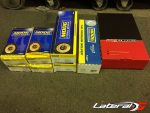
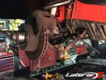
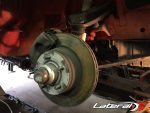
You can now also finish removing the spindle assemblies from the old suspension as we will be reusing them. A little side info on these. The spindles, caliper brackets, dust shields, rotors, etc were sourced from a 78 Dodge Magnum. The Magnum brake setups are the larger of the original type Chrysler disc brake setups with 11.75” rotors. All service parts such as rotors, calipers, brake pads, bearings, seals, and brake hoses can be source from NAPA using the 78 Dodge Magnum as a vehicle reference. It is a direct bolt on to the 69 Charger.
Installation: In With The New
Now that the old front suspension is out of the way we can start bolting on the new QA1 pieces. All these pieces are available individually, but we opted for one easy purchase of a full-vehicle suspension kit – we will be installing the rear later. It includes everything we need and all the parts bolt in to each other, so it’s easy to install. We could assemble the suspension out of the car and install it, but for this purpose, we will be doing it one piece at a time. The weight difference in the parts makes it very easy to do so.
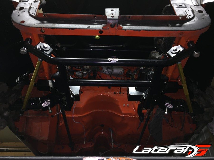
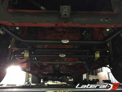
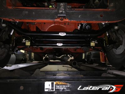
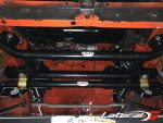
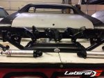
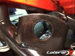
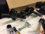
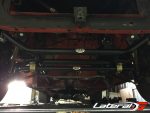
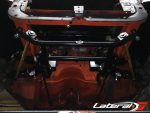
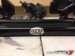
We start with the new K member. We asked QA1’s Bill Foley to tell us a bit more about the K-Member. “With its tubular design, it is engineered for maximum strength while providing more room for header and oil pan clearance,” stated Foley. It comes with supplied bolts to mount it to the car, and we used two of them on the rear; for the front, we opted to get longer grade 8 bolts. We run them up snug with an impact gun then torque to spec.
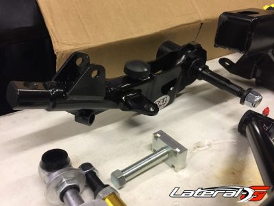
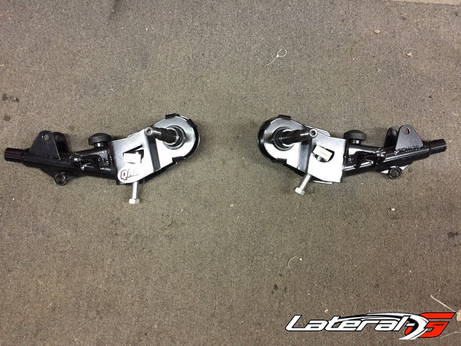
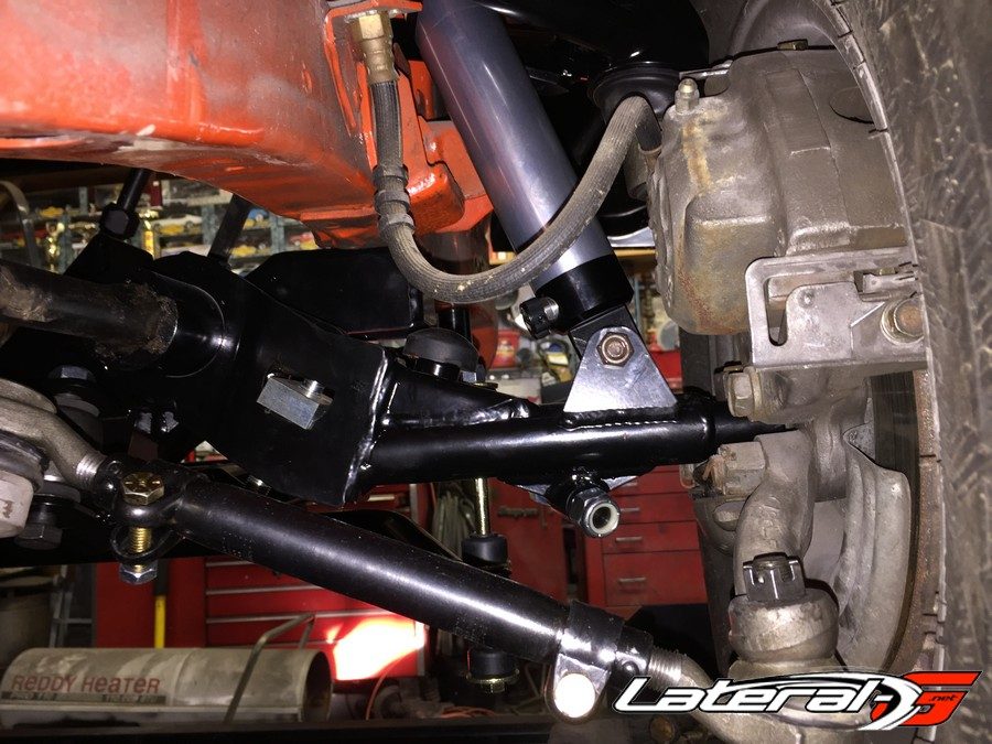
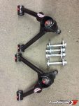
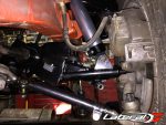
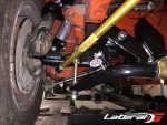
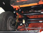
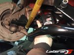
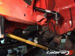
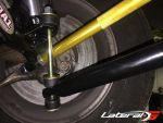
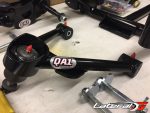
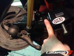
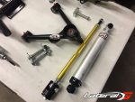
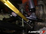
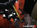
Next, control arm installation. Install the upper control arms first. The QA1 upper tubular control arms bolt in and increase caster by approximately 3-degrees to help tighten up our steering. Apply a little grease to the ends of the bushings and slide them into place until the eccentric bolts slip in. The lower control arms can go in next. Mopar factory lower control arms are known to loosen up as they get older. As a direct replacement for the factory arms, the QA1 lower controls arms are twice as strong as the OEM pieces without adding any weight. Insert the pivot of the arm through the K member using the supplied washer and nut to retain them but do not tighten yet. Just snug them up enough to seat them against the K member.
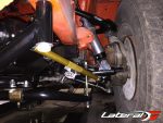
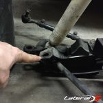
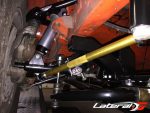
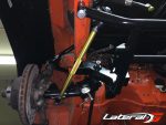
The adjustable strut rods are next to be installed. “These stock replacement arms eliminate the need for strut bushings and will help improve vehicle weight transfer while bolting in to the factory or QA1 K-member without modifications,” noted Foley. Make sure the adjuster nuts are loose so the rod can be lengthened if needed. Insert the strut into the lower control arm with the supplied nut. Fit the jointed end into the K member making sure the center of the rod end is seated fulling into the K member before installing the provided bolt and washer. Remove the slack out of the strut rod so it is snug up against the control arm and tighten the retaining nut to the control arm.
We can now install the spindle assemblies on the control arms. Slide the upper ball joint through the spindle and install the castle nut. The lower ball joint is integrated into the steering arm on the spindle. The lower control arm must be installed from the top of the lower ball joint. Make sure both ball joints are seated into the tapers and torque to spec then install the cotter pin through the castle nuts.
Now it is time to reinstall the torsion bars. A couple things you need to do before installing them. One, apply some grease to each end of the torsion bar. This helps to prevent corrosion on the cups they sit into Secondly, make sure the torsion bar receiver in the lower control arm is rotated all the way down up against the adjuster bolt. This is necessary so you have enough length in the adjuster bolt to properly set the ride height. Install the dust boot cover on to the torsion bar. Make sure you have the correct bar on the correct side of the car. Remember, they are side specific. If you have chosen to upgrade the stock torsion bars, refer to the installation instructions so they are installed properly. If you get lucky, they will slide right into place, but chances are they will need to be knocked into place with a few light taps from a hammer on the back where the bar goes through the frame. You may or may not need to raise the spindle slightly to insert the torsion bar into the lower control arm. This will vary from car to car. Finally, install the retainer clip and slip the dust boot over the groove in the frame cross bar.
Getting The Steering Straight
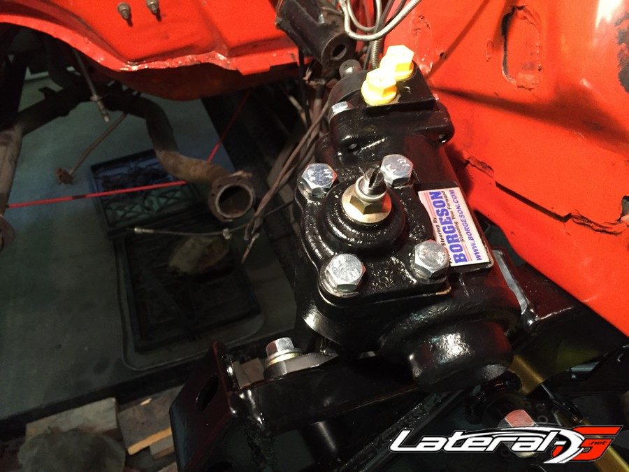
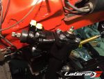
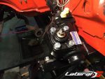
The next step is to install the steering box and linage. First up is the steering box. We caught up with Jeff Grantmeyer of Borgeson who filled us in on why this is such a great upgrade. “The factory power steering boxes were a 16:1 ratio and the manual boxes were a 24:1 ratio. The Borgeson box is not only a quicker 14:1 ratio but also features a modern rotary valve with a medium effort torsion bar that provides a true modern power steering feel and feedback. Additionally the box is much smaller and lighter than a factory power steering box providing much needed exhaust header clearance and a front end weight savings. This is the first completely new, not re-manufactured 50+ year old, steering box to be offered for the Mopar crowd,” stated Grantmeyer.
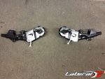
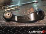
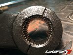
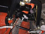
Three bolts hold the Borgeson box in place. The rest of the steering linkage are OEM type Moog components. The pitman arm can now be installed. First center the steering box then install the pitman arm perpendicular to the firewall. The pitman shaft and arm are indexed so that it goes on one way. Install the idler arm next with the supplied bolt and washers. You will need to reuse the original center link from the old steering as they are not produced due to them being a non wear item. Install the center link to the idler and pitman arms.
For the tie rods and adjuster sleeves, we like to assemble them on the bench then install the complete unit. We thread each tie rod into the sleeve so about five threads are engaged, then install them to the spindle and center link. This will allow you to turn each adjuster sleeve the same amount until the steering knuckles are close to pointed forward. Install the respective castle nuts, torque to spec and install the cotter pins.
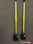
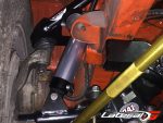
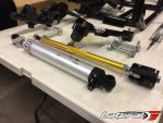
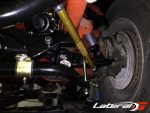
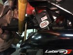
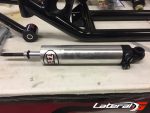
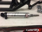
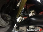
The shocks can be installed next. By adding adjustable shocks to our Charger, we’ll be able to really dial in the handling. “We sent the QA1 double adjustable Stocker Star shocks, which feature individual knobs for compression adjustment and rebound adjustment. By adjusting each independently, these shocks give you a much more modern ride while allowing you to make fine-tuned adjustments as you see fit or for different track conditions,” stated Foley. They install just like the factory shocks do, lower control arm to shock tower. Make sure to keep the adjustment knobs on the shocks pointed toward the inside of the for easy access. Tighten the top shock mount so the rubber mount just starts to squeeze out past the washer.
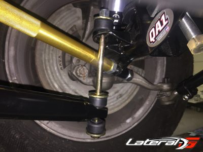
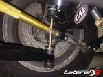
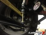
The final item to be installed is the anti roll bar. QA1 designed the K-member and anti-roll bar to work together, so you’ll need to use their bar instead of the factory sway bar. It comes with mounts and brackets that install directly to the K member. It’s easier to install the end links when the tires are on, the car is on the ground, and the suspension is loaded. That way, the strut rods don’t interfere. In our case, we also reduced the spacers to 2 7/8” instead of the supplied 3.5”.
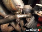
Overall, this installation is very easy to do without the engine in the car. It is doable with the engine installed, however, the difficulty increases substantially due to having to hang the engine from a hoist and deal with headers/exhaust along with any other things that may be in the way. The QA1 pieces are very nice pieces and enable better performance through more modern alignment settings as opposed to the factory setup. They should perform well on the road once the alignment is dialed in. Remember to find a GOOD alignment guy that will put the specs where they need to be vs what the factory specs are 0 to -1 degree on caster, ½ + on camber, and 1/8 on toe in, which are horrible for handling and radial tires. You want at a minimum of 2-3 degrees of positive caster, -½ to -1 degree on camber and toe in 1/16 – 1/8. The ride height MUST be set first.
For more information or to order, hop on QA1.net or give them a call at (800) 721-7761


