|
|

05-04-2012, 07:17 AM
|
|
Senior Member
|
|
Join Date: Jul 2008
Posts: 260
Thanks: 0
Thanked 0 Times in 0 Posts
|
|

Quote:
Originally Posted by 72Z/28

Nice  Are you going to have a junction block to hook the battery positive terminal, starter and the alternator hot wire? if so could you please post a photo of it where it is going to be mounted?
The reason why I am asking is that I have the battery mounted in the trunk like yours and there is a junction block mounted on the passenger side fender well. |
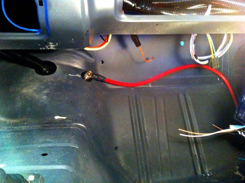
Yep. The main junction block that has constant power is located and mounted in the drivers fender area to the right of the pass-thru connector for the fuse panel. My main feed wire is 8 gauge and has a fuseable link connected to the selonid located in my trunk very close to the battery. The power wires that are ran to that main junction block go like this from back --->front in this order.
Main power wire - 8 gauge
Alternator wire - 8 gauge
Main fusebox power/interior pwr - 8/10 gauge cant remember what AAW ran
Main Ecu power - 2 leads
That pretty much covers the whole car. All my other powers will come off this block in some way. Hope that helps. Here are some pictures to show you.
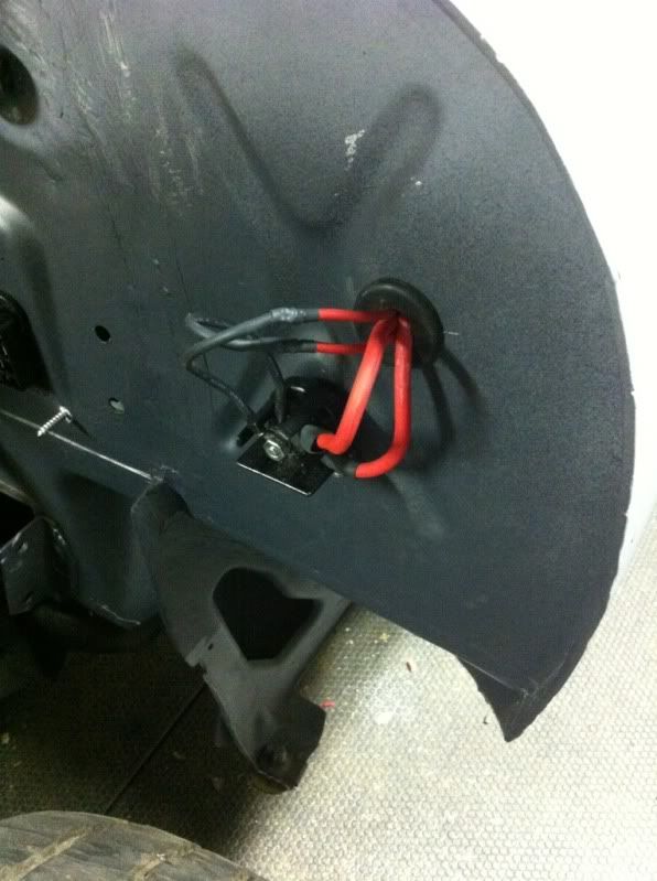
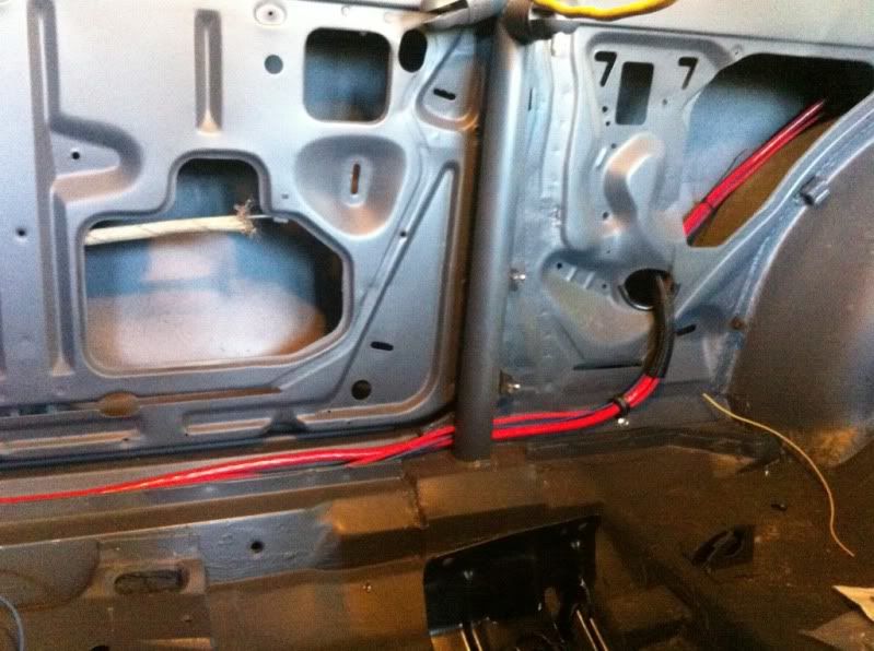
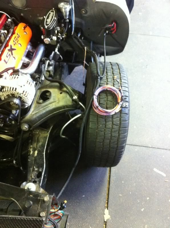
Heres the path that I routed the main 1/0 gauge starter wire, wire to the ignition, and the main 8 gauge for the distribution block in the drivers fender.
Starter wire runs through the pass toeboard as seen here.
Hope that helps give a better picture. If you have any other questions I can help with give me a pm and Ill shot you my cell number.

|
05-06-2012, 03:07 AM
|
 |
Senior Member
|
|
Join Date: Dec 2009
Posts: 374
Thanks: 4
Thanked 13 Times in 11 Posts
|
|
Thanks man for the info and the illustrations you provided. I will definitely send you a pm with some photos showing how stupidly the wiring was done on my camaro. Hopefully I am going to learn from you how to rewire some stuff.
__________________
72 Camaro RS:SOLD
68 Camaro:
LS6 Engine,Tremec TKO 600,5 Speed
Complete Speedtech Subframe Kit,Speedtech Torque Arm, 9" Rearend from Strange, Wilwood Brakes, Minitubbed, Hotchkis Subframe Connectors, FIKSE FM5s
|
05-06-2012, 02:04 PM
|
|
Senior Member
|
|
Join Date: Jul 2008
Posts: 260
Thanks: 0
Thanked 0 Times in 0 Posts
|
|
No problem. That's what we are all here for..without help I wouldn't be where I'm at now.
I ordered the last piece that I can think of to wrap the motor up. Radiator and all the pieces for the intake. All that should be here early next week. Then just have to finish some small wiring, mount the ecu, wrap up the gauges, either extend the coil wire plugs or get extensions, mount the coils, put the gaskets on the headers and tighten them down, fill the motor/radiator with coolant, run/route the PVC system. Cycle the key and check for leaks in the fuel system and coolant system and then let the heaven sing the sweet tunes of fire breathing power. Whoa I'm getting all excited...
So this weekend the old man came buy and we worked on tiddying up some lose wires, routing and securing the plug wires, fixing the oil leak at the adapter for the oil pressure gauge, running the power wire for the fuel system, and extending the wires for the map and cleaning that up. Next weekend I believe Timmy is going to come over so we can mount the pedal, ecu, and vaporworx stuff and mount the gauge cluster. Onto some quick pictures..


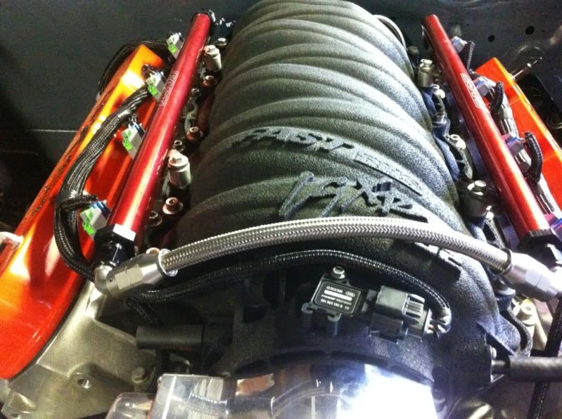
More to come soon..
|
05-07-2012, 02:09 PM
|
|
Senior Member
|
|
Join Date: Dec 2009
Posts: 374
Thanks: 4
Thanked 13 Times in 11 Posts
|
|
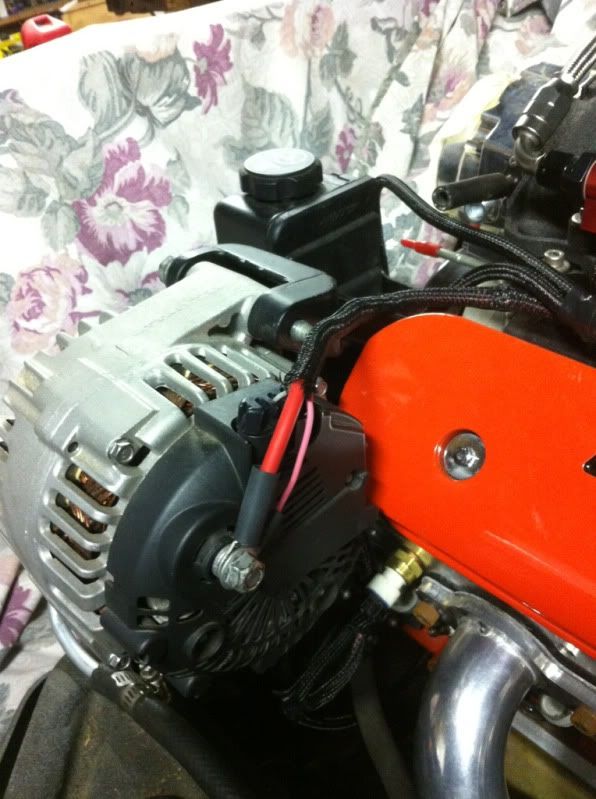
Thanks manand best of luckwith your project. I noticed that you hooked up a pink wire, which I assume is the S wire on the alternator pigtail, to the alternator post on the back side. What about the L wire, did you connect any resistor between the L wire and the alternator exciter?
The reason why I am asking is that I have got the same alternator, and there was only the L wire on the alternator pigtail connected to the alternator exciter wire, and the S wire was not connected. The alternator was not charging the battery when the S wire was not connected. So, I connected the S wire to post on the backside of the alternator similar to yours and started to get 14.4V at the alternator, but there is no any resistor between the L wire and alternator exciter wire. I actually don't know whether the alternator exciter wire is hooked to the dash cluster or to the PCM, and there is no charge light.. I tried to trace the exciter wire but know luck. The wiring harness and the EFI harness are from Painless.
I also realized that a Ford starter solenoid was installed on the fender well,

Honestly I don't know what the rest of the wires are for. 
__________________
72 Camaro RS:SOLD
68 Camaro:
LS6 Engine,Tremec TKO 600,5 Speed
Complete Speedtech Subframe Kit,Speedtech Torque Arm, 9" Rearend from Strange, Wilwood Brakes, Minitubbed, Hotchkis Subframe Connectors, FIKSE FM5s
|
05-08-2012, 07:52 AM
|
|
Senior Member
|
|
Join Date: Jul 2008
Posts: 260
Thanks: 0
Thanked 0 Times in 0 Posts
|
|
|
05-08-2012, 01:04 PM
|
|
Senior Member
|
|
Join Date: Dec 2009
Posts: 374
Thanks: 4
Thanked 13 Times in 11 Posts
|
|
Thanks dude for your cooperation;I will try to contact Mark and probably get the kit from him.
Once again good luck with your project.. 
__________________
72 Camaro RS:SOLD
68 Camaro:
LS6 Engine,Tremec TKO 600,5 Speed
Complete Speedtech Subframe Kit,Speedtech Torque Arm, 9" Rearend from Strange, Wilwood Brakes, Minitubbed, Hotchkis Subframe Connectors, FIKSE FM5s
|
05-10-2012, 07:14 AM
|
|
Senior Member
|
|
Join Date: Jul 2008
Posts: 260
Thanks: 0
Thanked 0 Times in 0 Posts
|
|
|
05-13-2012, 07:17 PM
|
|
Senior Member
|
|
Join Date: Jul 2008
Posts: 260
Thanks: 0
Thanked 0 Times in 0 Posts
|
|
|
05-14-2012, 10:16 AM
|
 |
Lateral-g Supporting Member
|
|
Join Date: Oct 2006
Location: Ma
Posts: 8,491
Thanks: 939
Thanked 342 Times in 231 Posts
|
|
Your making some great progress. Thats a sweet looking radiator it will definitely be plenty of cooling. Nice work.
|
05-23-2012, 07:48 PM
|
|
Senior Member
|
|
Join Date: Jul 2008
Posts: 260
Thanks: 0
Thanked 0 Times in 0 Posts
|
|
Thanks man..
Ok so may photobucet is down..hate that sometimes anyway.. Been really pushing on the car could have done it with out the help from family, friends, John over at psi and Carl at vaporworx..both great companies to work with. For the first start the car would run 2-3 seconds and stall. We then scanned for codes and where getting cam and crank. After talking to John we realized the cam signal was wrong and fixed it, again thank you John. The car then fired but was running rough...realizing there is two large vacuums at the back of the manifold that need to be plugged. Once those where closed with my buddies finger here's what we have...
http://s1163.photobucket.com/albums/...t=2475b1dd.mp4
Now the crank code is still coming up which im told I need to get a tech II and do a relearn. Going to address that get some plugs for the intake and I also ordered a fuel pressure gauge to dial in the fuel pressure to make sure she's getting enough fuel.. Hopefully they should get her running well.
Other than all that I need to get the car ready for the engine break-in and tune..which means it has to be drivable. The brake lines are roughly ran but need to be finalized and all the end need to be cut and reflarred to fit the wilwood distribution valve, then bleed. Need to fill both rear and transmission with fluid, put the drive shaft in, bleed the clutch, put the steering box in and steering column back in, and button up all loose end/bolts.
Much more to come..
|
 Posting Rules
|
You may not post new threads
You may not post replies
You may not post attachments
You may not edit your posts
HTML code is Off
|
|
|
All times are GMT -7. The time now is 07:08 PM.
|


 Brian Hobaugh SCCA National Tour June 2014
 First Hemi 'Cuda Convertible Ever Built
 Short clips: Goodguys Pleasanton autocross and pit videos


 Linear Mode
