...

Go Back   Lateral-g Forums > Technical Discussions > Chassis and Suspension
User Name
Password


Reply
 
Thread Tools Display Modes
  #1  
Old 05-09-2009, 11:01 PM
JRouche JRouche is offline
Senior Member
 
Join Date: Oct 2008
Location: Ventura County
Posts: 253
Thanks: 0
Thanked 0 Times in 0 Posts
Default Air ride, Watts link and Sway bar install...

Hey guys. This is a re-run from a couple other sites, sorry if its a bore

My car is a 62 Chevy II Nova coupe that I bought in 1995. Was just gonna keep the 350/350 combo and have fun driving it. But the front drum brakes were just too scary. So I installed a Mustang II front (build pics on that later) so I could have disc brakes. And with the nice front I wanted a lil more at the rear. So I bought an Art Morrison 4-link rear clip and installed that. Built an edelbrock injected engine then had a few changes in life. Family (wife wanted kids), moved to a house (was in a condo) and my job was demanding more, more, more. So the car, still un-driven was put on the back burner for many years.

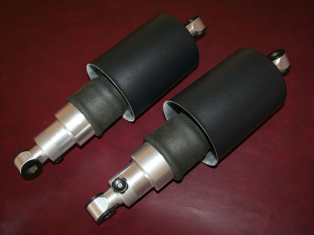
I retired last year so full steam ahead on the car. The 4-link was used for simplicity of the build back in 95 when not much was available for the Novas. But after thinking about it I didn't like some of the characteristics of the 4-link. Narrow pan hard bar and the coil over placements. I did alot of looking around and decided to use Air Ride technologies air ride system with the shockwave air springs and hydraulic shocks. And I couldn't get a longer pan hard bar in there, the one I had was only 24" long, too short, the rear would wallow around on the street, yeah, I did get to drive it around on the local neighborhood streets a lil. So I liked the idea of a watts link. The kits that are out there are great!! But again, I was limited on space so I made up my own. No real cost savings..

So here are some pics of that install. It was fun, and frustrating at the same time..

I have never worked on cars before, this is my first. And I never welded before. So you will see alot of odd looking ideas and some bad welds. I know cause I have to look at them everyday LOL But,,, its the best I can do and its solid so Im not afraid of it coming apart.

Anyway, enough of my back peddling trying to justify the rough looking work. Enjoy and please comment, any of your knowledge will be great for the next project (71 Fiat spider with a large-ish V6. JR


When I bought the car, 1995....


Art Morrison rear clip.


After the rear clip install in 95. Thats kinda covered in another post of mine. Wont bore ya more than Im gonna


First job at hand was the lower shockwave mounts. I used some 9" leaf spring perches cut in half. Had to use two cause they aren't exactly in half. They are heavy duty brackets, 1/4" bent steel. Some additional 1/4" plate to add to the beef of it. I was going to be using the holes in single shear for the shock mounts and I thought a 1/2" would be better than a 1/4" shear plane.


TIG welded up and ready to go.


MIG welded onto the axle housing. I didn't disassemble the housing. I did make sure all the weight was off the housing for the weld. And I welded in about 1.5" sections and cooled the area with a damp rag in between. Took a long time but it never got the housing tube past warm to the touch after cooling. And I beveled the heck out of the brackets so the penetration is pretty good. They aren't going anywhere.


Next was the upper mount. I get alot of use outta this lil 7" band saw.. 1/2" plate.


Reply With Quote
  #2  
Old 05-09-2009, 11:03 PM
JRouche JRouche is offline
Senior Member
 
Join Date: Oct 2008
Location: Ventura County
Posts: 253
Thanks: 0
Thanked 0 Times in 0 Posts
Default

Plasma cut the extra off to make the right shape.


Shock used for placement of the upper mount. It is all at ride height. Coilovers still in place. I made some stainless steel spacers so if I need to adjust the 4-link in the future I have some wiggle room inside of the upper mount. The 4-link bars are at their shortest length right now. If I adjust them it may move the rear end back some.


Time to weld in the uppers but no way did I want the shocks in there, rubber!! So I made these links that are the same length eye to eye as the shocks at ride height. And they were gonna be needed for the watts link welding too. They helped to get each side of the car exactly right for height when making the watts. I measured everything so many times, jumping back and forth. But the sides are equal to within a 32nd of and inch. And thats axle to frame and body to ground.


Plasti-coat bed liner paint I love so much, you will see it on everything.


Finally, the coilovers are outta there, full weight on the struts I made. Ill need the additional space, going be filled up soon.


Reply With Quote
  #3  
Old 05-09-2009, 11:04 PM
JRouche JRouche is offline
Senior Member
 
Join Date: Oct 2008
Location: Ventura County
Posts: 253
Thanks: 0
Thanked 0 Times in 0 Posts
Default

I was a lil pissed. AR sent me the shockwaves with the optional air can (big ugly can over the bag) they sell for a hundred bucks. I didn't want it, looked cheesy IMO.. But. I thought I would give them a chance. If I didn't like the look I could remove them later. No, they didn't charge me for them. Guess they were having alot of problems with guys tearing the bags due to close tolerances. So I really didn't want a massive aluminum can sitting in there. Time for some plasti-coat!!

Ghetto paint booth LOL


So thats the coilover swap. Watts link next..

Watts link time.. I stole some ideas from just about everyone. Looked at ALL the pics out there. Came down to space limitations. I ended up just going simple.

I bought the center pivot from Tim over at Fay's 2. Nice piece. And the DOM tube and weld in ends from another company. I used QA1 rod ends, some of the best out there. I used 3/4x5/8" instead of the 3/4x3/4" Tim uses so I had to make some shims for the center pivot arm mounts.

Now bolts. I could go on and on about bolts. But basically I looked into some NAS (aircraft) bolts cause this stuff is in shear, watts and shock mounts and I wanted the proper grip length. UMMM!! 90 bucks a bolt. I called seven companies all over the US. Yeah, all the regulars, AC spruce, coast fabrication, and all the same. So there are "grade 9" bolts available. Fastenel, Grainger (PFC) and CAT were who I used to get the right length bolts so ALL the shear joints had the grip in shear, never the threads. The grade 9 bolts are all 180k PSI. And really, they are great fasteners and the price was right. Still a couple hundred in bolts.

Anyway.. Some pics....

This is the original pan hard bar, very short, gotta go.


My shopping list. Prolly four dealers here


Links TIG welded up. I know, not the greatest welds but they are HOT and deep. Had to chase the threads after welding.


And the center pivot mounting. Started as a 1/2" plate. I drilled the 3/4" holes under sized and reamed to a tight slip fit for the center bolt. Then clamped it up to my welding table, its a beast of a table. I used some 2x2" 1/4" wall tube. The stuff is very stiff. Tacked it up, both sides, heavy beveling at the joints then took it outside to put some real heat to it. MIG welded it up tight. Sanded the welds down on one side to have clearance for the center pivot and it helped the appearance too.


Reply With Quote
  #4  
Old 05-09-2009, 11:06 PM
JRouche JRouche is offline
Senior Member
 
Join Date: Oct 2008
Location: Ventura County
Posts: 253
Thanks: 0
Thanked 0 Times in 0 Posts
Default

Test fitting it up in the car. I used the same 2x2" tube for the cross member to attach it to the frame. I made some angled braces out of heavy walled 2x1.5" tube that would be up above the line of site. Welded it in. That my friend was a drag. Up under the car, leather draped everywhere on the car and myself as Im on my and had to be directly under the weld to see it. And I had the welder on full tilt, welding the 1/4" wall tube to the frame. Heavy bevels again. But I wanted a SOLID connection. Nothing worse than cold joints, not a one here. But it was tight, just to get the gun tip in there, and I dont pull the trigger unless I can see the joint (auto helmet is a must). Wasn't diggin this part at all.


Next was the axle tube mounts. Stole this idea from Tim at Fay's. Sorry. Heavy duty 1/4" steel axle clamps. Oh, they dont move at all with just the slightest bolt tightening. Clamp them down tight and they are NOT gonna slip. The full contact makes them so solid. I was kinda wondering if they would deform my axle tubes if I really put the wrench to the bolts so I clamped them up to a thin walled exhaust tube I had. And really laid on the wrench. Didn't deform the 16ga tube at all, no worries for the axle tubes. Oh, and there was alot of pre-weld measuring steps, alot. The arms are clocked different for each side.


Welded while clamped.


Ready to bolt up


Reply With Quote
  #5  
Old 05-09-2009, 11:07 PM
JRouche JRouche is offline
Senior Member
 
Join Date: Oct 2008
Location: Ventura County
Posts: 253
Thanks: 0
Thanked 0 Times in 0 Posts
Default

Oh, and bolts.. Some of the fasteners if yer interested. These are all "grade 9" bolts. But I wanted to show how they are hardened. Pretty cool actually. I had to turn down the watts link arm pivot bolts to get the right grip length. I really noticed how hard the outer case hardening was on the bolt and how it got softer at the center. You can see it on the turned end. And when I say hard I mean it. I was using some good carbide inserts and for a second I thought about grabbing the CBN inserts. But I just cranked up the RPMs and let the sparks fly, I love hard turning… But you can see the softer center of the bolt. Thats a good bolt. Not just a bulk hardening of the entire bolt. Has a hard outer surface, pretty deep really, and a softer core. Dont ever let anyone tell you a grade five bolt is better cause a grade 8 bolt is too hard, its just comical some of the threads I read.


Ok, so I'm gonna wrap this up. Sway bar is next. I looked into the sets available. Again, space was an issue, and rates really. My lower roll center with the watts link is gonna give more body roll. So I asked and looked around alot for a good starting point for the bar spring rate needed. Kinda a shot in the dark really without driving the car. But I decided on around 295lbs for the bar. And I already decided on a three piece bar from Speedway Engineering. They have some great stuff, many three piece bars you see labeled under a diff name may be their bar.

Its a straight torsion bar, solid or hollow, with splined ends. The arms are splined also and they come undrilled for the links. So you determine the rate you need and find the length bar that will suit the space issues. Thats where I screwed up, had to buy another bar cause my tires were too close to the first bar's arms. So anyway, get yer rates you need, the length bar that fits and drill the arms for the proper rate. They can be drilled from 10 to 15 inches for various rates.
I ordered the low profile pillow blocks. They come drilled to bolt them to the frame. I wanted a different mount. I made some brackets to bolt through the frame sideways instead of up through the frame.

I had intentions of being able to slide the mounts fore and aft to adjust for sway bar rates and just change the arm mounting holes. Not gonna happen that way. Too difficult to drill perfect holes through the frame. So I'll just get a different bar, same length but different rate if I need to change the rate later down the road. Gotta drive it first to even get to that point. So, here are the pics...

Made some brackets for the pillow blocks. It was a slow process. There is rubber in there. So I plug welded the holes up, cooled with a wet rag in between, made a weld, cooled, and so on. Never got it hot on the rubber side. LONG process.


They weren't set up with zerks so I drilled and tapped some holes and put on some zerks. I also lightly grooved the bearings in an outward spiral direction to allow the grease to move to the entire surface of the bearing. It seems to work, I have done it on some bed mills too.


Made a lil tool to help with holding the bar and pillow bocks up while I figured out the placement.


Arms drilled and reamed for the links.


Measuring up the link mounts. I can conveniently use the flat I welded to the spring perch earlier. Yeah, it was planned. Yeah RIGHT!!!

Reply With Quote
  #6  
Old 05-09-2009, 11:08 PM
JRouche JRouche is offline
Senior Member
 
Join Date: Oct 2008
Location: Ventura County
Posts: 253
Thanks: 0
Thanked 0 Times in 0 Posts
Default

Some Zoop seal to protect the links?? I'm just looking for stuff to Zoop, have so much left over from the wheels I did..


Ok, I know, long thread. Here are the last pics as its all done..


Comparison………
Before

After


On the ground, not ride height but sitting on the bump stops.


Sorry for the long thread, I still had to edit out a hundred pics. And I tend to get a lil long winded LOL The front end is jacked three feet in the air and the control arms are on the bench getting welded on this week. Hope the front goes faster. Thanks for reading, JR
Reply With Quote
  #7  
Old 05-10-2009, 12:16 AM
jack67rs's Avatar
jack67rs jack67rs is offline
Senior Member
 
Join Date: Dec 2004
Location: Glendale, AZ
Posts: 237
Thanks: 0
Thanked 3 Times in 3 Posts
Default

great shots! nice work also, keep us posted
__________________
Tangerine 1967 camaro "Octane"
https://lateral-g.net/members/hodson/

Hot Rod cover Feb. 2008 "Homebuilt Hero"
Camaro Performers feature Car March 2008

Video on Webridestv.com
http://webridestv.com/showvideo.aspx?video=55306
Reply With Quote
  #8  
Old 05-10-2009, 01:39 AM
Vegas69's Avatar
Vegas69 Vegas69 is offline
Senior Member
 
Join Date: Dec 2006
Posts: 8,692
Thanks: 87
Thanked 215 Times in 120 Posts
Default

You have some serious talent. You must have 500 hours in that job.
__________________
Todd
Reply With Quote
  #9  
Old 05-10-2009, 07:48 AM
simbad's68 simbad's68 is offline
Senior Member
 
Join Date: Dec 2006
Location: Cypress, TX
Posts: 235
Thanks: 1
Thanked 0 Times in 0 Posts
Default

Nice work!! Keep the pics comming.
Reply With Quote
  #10  
Old 05-10-2009, 09:26 AM
DRJDVM's '69's Avatar
DRJDVM's '69 DRJDVM's '69 is offline
Senior Member
 
Join Date: Jul 2004
Location: Manteca, CA
Posts: 1,299
Thanks: 2
Thanked 48 Times in 26 Posts
Default

Very nice work.... I'm impressed.

So you decided to take the Air Cans off

I like the braided line running to the shocks.... I may just do that on mine too....
Reply With Quote
Reply


Posting Rules
You may not post new threads
You may not post replies
You may not post attachments
You may not edit your posts

BB code is On
Smilies are On
[IMG] code is On
HTML code is Off

Forum Jump


All times are GMT -5. The time now is 06:28 AM.


Powered by vBulletin® Version 3.8.11
Copyright ©2000 - 2025, vBulletin Solutions Inc.
Copyright Lateral-g.net