...

Go Back   Lateral-g Forums > Technical Discussions > Chassis and Suspension
User Name
Password


Reply
 
Thread Tools Display Modes
  #1  
Old 03-20-2006, 02:21 AM
69MyWay's Avatar
69MyWay 69MyWay is offline
Supporting Member
 
Join Date: Feb 2005
Location: Clinton, IL
Posts: 1,256
Thanks: 8
Thanked 13 Times in 6 Posts
Default Getting racked

Just now wrapping up the rough-in installation of a 97 Grand Am rack in my 69 Vette.

I won't have time to get back to it until this weekend. I will be running a pair of passenger side tie rods from the 97ish grand am. I can't start to bump steer test it until after those are in. Having to get lengthened adjuster bolts for the tie rods.

The new tie rod assembly will be coming from the center of the car (longest possible tie rod length). This should help reduce bump steer issues.

http://mcspeed.homestead.com/Rackinstall.html
Reply With Quote
  #2  
Old 03-20-2006, 02:56 AM
69MyWay's Avatar
69MyWay 69MyWay is offline
Supporting Member
 
Join Date: Feb 2005
Location: Clinton, IL
Posts: 1,256
Thanks: 8
Thanked 13 Times in 6 Posts
Default

BTW, if it looks too low...no worries. Notice the sidepipes on the driver side. The rack hangs no lower then them, and my oil pan is deeper than that!
Reply With Quote
  #3  
Old 03-20-2006, 05:14 AM
Twin_Turbo Twin_Turbo is offline
Senior Member
 
Join Date: May 2005
Posts: 104
Thanks: 0
Thanked 0 Times in 0 Posts
Default

Why in the center? sure, if you put them in the center you get the least angular difference over the suspension travel, however you can also put them in the correct posiyion so they have the same angular change over travel as the steering knuckle has resulting in absolute 0 bumpsteer.

Look at this picture, it's all about extending the ball joint to cross shaft lines, where they cross you have your instantaneous center, then from there go to the steering arm. Where all this intersects the line between the 2 cross shafts is where the tie rod end should be, the angle can be fine tuned by spacing the steering arm side. It will be difficult and time consuming to do but you should be able to get it very close to ideal, that sure makes fine tuning easier later on 9w/ bumpsteer measurements) I did all that with the entire front clip off the car, much easier that way and I know you won't be able to do that.


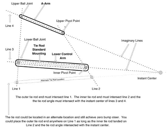
What they call "alternate" position is where the tie rod will roughly be, slightly lower than the lower control arm.

Where it says line 2 you see the inner pivot for the tie rod, THAT'S where the hole in your rack's center plate should be. I know you spoke to Norvalwilhelm about this, look at his pics, that's exactly the position of the eye on his center link, he modified the stock one to reposition the mounting hole.

Don't worry about line 1, it's purely theoretical, there's no way the line will be in the same plane as the 2 balljoitns since the steering arm is further back and you have to accout for the ackerman geometry putting the steering arm hole slightly further inboard from the spinde steering axis.
Reply With Quote
  #4  
Old 03-20-2006, 05:19 AM
69MyWay's Avatar
69MyWay 69MyWay is offline
Supporting Member
 
Join Date: Feb 2005
Location: Clinton, IL
Posts: 1,256
Thanks: 8
Thanked 13 Times in 6 Posts
Default

That is a great explanation of that diagram. I have been looking at it from Corvette Forum and not 100% sure how it lays out.

Was speaking to my buddy Dave at www.tropiczoneracing.com this weekend about different angles, etc.

I won't know anything until I can get the gauges set up to run the tests. I am going to start in the middle and work my way out. I will need to build a center mounting plate to change the height and position of the inner tie rods.

Thanks for the info and the explanation.
Reply With Quote
  #5  
Old 03-20-2006, 05:31 AM
Twin_Turbo Twin_Turbo is offline
Senior Member
 
Join Date: May 2005
Posts: 104
Thanks: 0
Thanked 0 Times in 0 Posts
Default

That's the neat thing about the center take off, if you get it wrong you can simply build a new center place. I have a front steer end take off rack and because of the fixed tie rod end locations on the rack shaft you have to position the entire rack dead accurate on the frame, if you get it seriously wrong you're screwed. There's some adjustment possible by shimming the rack and the tie rods ends but nothing more.

How did some of the guys over on CF do their bracket? The only 2 I've seen are mrvette (gene) and keith (427 / corvettengineering) and I think both went to the put them in the center approach right??

Looking at the plate from speeddirect it looks like they have or tried to put the holes in the correct position (although it will differ from car to car due to tolerances, frame sagging and so on)
Reply With Quote
  #6  
Old 03-20-2006, 01:59 PM
69MyWay's Avatar
69MyWay 69MyWay is offline
Supporting Member
 
Join Date: Feb 2005
Location: Clinton, IL
Posts: 1,256
Thanks: 8
Thanked 13 Times in 6 Posts
Default

You are exactly right about the steeroids and the other guys that built the center plate with the inner tie rods offset to center them and position them in a more correct location.

I will already have the GA tie rods so I am going to have some fun hooking them up and measuring. That won't cost anything but time and I can get an idea where it sits now.
Reply With Quote
Reply


Posting Rules
You may not post new threads
You may not post replies
You may not post attachments
You may not edit your posts

BB code is On
Smilies are On
[IMG] code is On
HTML code is Off

Forum Jump


All times are GMT -7. The time now is 09:17 PM.


Powered by vBulletin® Version 3.8.11
Copyright ©2000 - 2025, vBulletin Solutions Inc.
Copyright Lateral-g.net