|
|

02-09-2017, 07:08 AM
|
 |
Lateral-g Supporting Vendor
|
|
Join Date: Jan 2017
Posts: 27
Thanks: 0
Thanked 0 Times in 0 Posts
|
|
How much down force are you guys anticipating the front splitter will create? The overall project looks great. I'm glad to see that someone appreciates the color white as much as I do.
|
02-09-2017, 08:21 AM
|
 |
Member
|
|
Join Date: Nov 2009
Location: Dallas, TX
Posts: 22
Thanks: 2
Thanked 0 Times in 0 Posts
|
|
Quote:
Originally Posted by JohnJ@RideTech

How much down force are you guys anticipating the front splitter will create?...
|
John, I don't know. I've found modeling, even fairly sophisticated modeling, to be more useful in determining amount of change we can achieve, but not accurate enough to give us accurate absolute measurements. This has been true for aero, tire testing and to a point, suspension geometry.
The plan is to build both the splitter and diffuser to the limits of the compromises we have to work with, and then balance it with the adjustment available in the wing.
FWIW, my education (years ago) was in hydrodynamics and aerodynamics. I studied to design racing sailboat hulls and sail shapes.
__________________
Jason McDaniel - Vorshlag R&D
|
02-09-2017, 02:31 PM
|
 |
Senior Member
|
|
Join Date: Apr 2012
Posts: 253
Thanks: 0
Thanked 0 Times in 0 Posts
|
|
There is soooooo much want in this build!
|
05-15-2017, 01:52 PM
|
|
Senior Member
|
|
Join Date: Mar 2014
Location: Plano, TX
Posts: 160
Thanks: 6
Thanked 67 Times in 33 Posts
|
|

Project Update May 13th, 2017: Lots of little details to show in this 3-part update (well, on most forums). We will show transmission tunnel structure fabrication, aluminum interior and firewall panels construction, sheet steel cowl structure, custom wiper motor mounting, body panel assembly, Tilton fluid reservoir mounting, defroster box installation, composite dash panel installation, shifter/linkage installation, and more.
TRANSMISSION TUNNEL & SHIFT LINKAGE
The design of the transmission tunnel structure is important on this car because of several reasons: it has to house the driveshaft (which due to the live axle will move vertically), it has to house the X-merge and both main pipes of the dual 3" exhaust, the tunnel has to leave interior room for both the driver and passenger, it has to incorporate a flat floor design (so it is taller than normal), and it will have removable panels - for easier access during maintenance and repairs. The tubular structure and panels should also provide additional structure to the center of the chassis.
 
Ryan had the shifter mount structure above already built, which was based on some earlier exhaust mock-ups and from the customer's driving position, when he did a "test sit" in several seats. He then created tubular structure to tie this into the rear bulkhead/crossbar structure, which put the shifter on more solid footing. The shifter will also have a Nomex shifter booth covering the opening in the tunnel.
 
This tubular structure will be used to mount the aluminum sheet panels and tie into the firewall forward, shown in another section below.
 
The remote shifter was mounted to this structure, then the rod ends and shift linkages were built (2 of the 3). This was done before construction of the exhaust system to help route the 3" exhaust tubes away from the rods. All of this fits inside the tunnel, which can be accessed from below or removed from above.
FRONT END ASSEMBLY
Ryan (our CNC operator) helped (fabricator) Ryan reassemble the front sheet metal and splitter to the chassis. This was the first time all of the front body panels and sanded/blended front splitter have been on the car together.
 
This was needed to align the height of the floor panels with the main plane of the splitter.

We also needed to see where the body panels would need to meet up with the soon to be built firewall.
 
The front flares and canards were also reattached to the front sheet metal.
COMPOSITE DASH INSTALLATION
Using a metal dash in a car built like this doesn't make a lot of sense, so we ordered a VFN fiberglass 69 Camaro dash with the customer's blessing. Installing this inside of the elaborate roll cage structure would prove to be a challenge. Nothing is ever easy on a race car
 
First, the bottom section of the OEM shaped dash had to be clearanced to clear the cage mounted steering column brackets that were used. These billet brackets hang down from the "dash bar" of the cage, shown below.
 
After the bottom section was clearanced it cleared the column, but there was no way to get it in between the A-pillar down bars and FIA compliance vertical bars in the roll cage structure.
continued below

|
05-15-2017, 01:52 PM
|
|
Senior Member
|
|
Join Date: Mar 2014
Location: Plano, TX
Posts: 160
Thanks: 6
Thanked 67 Times in 33 Posts
|
|
continued from above
 
The dash had already been clearanced on the outer edges for the A-pillar bars but to fit into this tight space it would need to be put into 3 sections. The best cut locations were chosen and marked, then Ryan carefully cut the dash panel with a body saw, down along the complex shape of the dash.
 
To re-join these 3 sections inside the car, the outer two "ends" of the fiberglass dash had "doubler plates" added, which were hand made from aluminum sheet. These were Cleco'd to the panels and tested/fitted, before being epoxy bonded and riveted to the main composite panel. The center section of the dash will unbolt from threaded rivnuts added to the doubler plates.
 
Here the 3-piece dash was fitted and assembled between the jungle gym of cage tubes, joined along the two joints / doubler plates with Clecos. Once this was fitted and mocked up in the car, the outer dash sections' mounting brackets could be built to attach to the cage.
 
Above left you can see one of the steel mounting brackets being fitted. This was then TIG welded to the roll cage bar and Clecos joined it to the dash panel (which will be replaced by bolts and nuts at final assembly). Above right is the other bracket, welded to the cage and Cleco'd to the left end of the dash. The 3-piece dash is now re-assembled and mounted into the car. The seams where the dash join together are tight, and once bolted together with more than a few Clecos, it will have an even cleaner finished look.

The dash was mostly mounted at this point, with a bit of a bow in the fiberglass on the unsupported bottom edge. We added additional mounts to the dash when the forward transmission tunnel was completed (shown out of order above). A bit more trimming was necessary at the bottom of the dash, due to the extreme driver setback and long steering column length. The dash panel is there for cosmetic reasons, as there will be a digital dash mounted to the column closer to the driver.
DEFROSTER MOUNTING
At the beginning of this project we discussed with the customer about moving to an aftermarket heater box, which can provide "defrosting". We have done the same compact heater box on many of our race car builds. The brand new, lightweight, and compact heater core + blower motor box will be mounted (and completely hidden) underneath the VFN dash panel then ducted to the front defroster vent sections at the base of the windshield. You can see the weight below (7.48 pounds), as well as a modern S197 Mustang factory heater/evap core blower box, which is huge (and 20.7 pounds).
 
On colder/wetter track days this will be invaluable. We started on the defroster mounting along with the central dash mount and trans tunnel tubing structure at the same time. The heater box is one of the last things that needs to be mounted before we can start plumbing various systems.
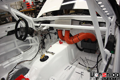 
This is the same heater box unit mounted into an S197 Mustang race car we built a few years ago. Plumbed into a custom plenum that pumps heat through the defrost vents at the base of the windshield, this unit has performed flawlessly for over 4 years.
 
The fiberglass dash will also be trimmed around the original cowl holes for at least two defroster vents, as shown above at left. The unit will be mounted behind the faux dash panel and on top of a plate mounted to the transmission tunnel.
continued below
|
05-15-2017, 01:55 PM
|
|
Senior Member
|
|
Join Date: Mar 2014
Location: Plano, TX
Posts: 160
Thanks: 6
Thanked 67 Times in 33 Posts
|
|
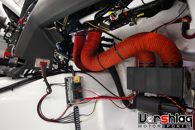
continued from above
 
To mount the defroster / heater core / blower motor enclosure required a section of the tunnel covers be built, then a lower "box" frame - both from aluminum. The lower box section was cut and bent to shape, then it was bolted to the tunnel section shown below.
 
This all made for somewhat tight confines under the dash, with the various components hidden under there - wiper motors, defroster, dry sump oil tank, etc. I will show the wiper motor mounting in a section below. But here the defroster box is mounted and ready for heater hose plumbing and some air 3" hose to the windshield base vents, to be shown in a future update.
continued from above
TILTON BRAKE & CLUTCH FLUID RESERVOIR
The triple reservoir Tilton unit shown below will contain fluid for both brake master cylinders (front and rear channels) as well as the clutch hydraulics. A custom aluminum bracket was fabricated and two threaded pylons were welded to the cage dash bar.
 
These two pylons protrude through the dash panel, but after the two mounting bolts are removed the center dash panel can be unbolted and pulled out of the way for maintenance behind it.
 
These remote reservoirs are popular in racing - you want to mount this just far enough away from the driver to not be a hazard, but close enough to be able to see fluid levels. Levels can drop from either pad wear (over a very long stint) or due to a leak in the hydraulic systems. Always good to have that visible while driving. We will plumb these to the floor mounted pedals/masters later in the build.
INTERIOR ALUMINUM PANELS
Most of the aluminum interior panels were built over 4 different days. These are needed to separate the passenger compartment from the exhaust, driveshaft, heat and noise from the engine bay. This, along with the firewall panels, forms a barrier from hot fluids and fire ahead or underneath the driver, in case something goes awry. The tunnel sections near the driver will be double walled with insulated panels on the inside, to limit heat transfer to the cabin. We will show the inner panels at a later date.
 
Previous sections in this series of posts showed some of the interior panels going together, and in reality there were several tasks happening at once - tubular structure, defroster, dash mounting, reservoir mounting, firewall and interior panels were concurrent tasks - but I am trying to show them separated here for clarity.
 
Templates in cardboard were made for various panels. These templates were then transferred into 3003-H14, .063" thick aluminum sheet. These metal panels were marked, sheared, bent, trimmed, deburred, fitted, and then drilled for mounting holes. Depending on the location the panels will be either riveted or bolted in place.
 
Step by step each template was turned into an aluminum panel. The picture above shows how some of these panels join to the composite dash. The passenger foot well area is also very different than the driver's side, to clear the massive dry sump oil settling tank, which has a complicated firewall structure around it. There is still tons of leg/foot room due to the front seat setback.

This is a close-up of how the dash was trimmed to fit against the taller than stock transmission tunnel structure and paneling. It makes for a very nice fit, once complete.
continued below
|
05-15-2017, 01:56 PM
|
|
Senior Member
|
|
Join Date: Mar 2014
Location: Plano, TX
Posts: 160
Thanks: 6
Thanked 67 Times in 33 Posts
|
|
continued from above
 
The complex shape around the exhaust header on the passenger side was taped together at first. These sections were then tack welded in the car, removed, and fully TIG welded on the bench to make a single panel. The shape of these panels will give the most interior room and allow for the unique, above floor exhaust routing.
Additional interior panels behind the driver compartment are shown in a later section. Plus there was some bleed over of work from the firewall panel fabrication in the interior panel task, due to the complex nature of the dry sump enclosure, which I will show below.
ALUMINUM FIREWALL PANELING & COWL
The firewall paneling took a chunk of time, but there was also a steel upper cowl structure being added, as well as the side sections that joined the firewall to original front unibody sections (under the A-pillars). Not to mention the complicated panels around the dry sump tank. I've broken up this task into sub-sections, which spanned over 5 different days of work.
FIREWALL - MAIN FLAT PANEL
 
The first main firewall panel was the biggest and easiest to make. Big flat section that covers 80% of the firewall. That was made from the same .063" aluminum 3003 as the interior panels, which is appropriate for fire protection, strength, and weight.
 
This was clamped to the square steel tubing added previously, which replaced the rusty OEM cowl section starting from about 4" below the base of the windshield.
 
An outer section on the driver's side was bisected to go around two chassis/cage tubes ties into this main flat panel section, shown above. Moving the engine back significantly required these custom firewall panels, of course.
FIREWALL - UNIBODY STEEL SIDE PANELS
Part of the new tubular cowl structure had been built when the car was still on the chassis table, shown below. But there were still large open gaps between this section and the forward portion of the unibody, as well as at the vertical edges. We needed some metal paneling here to keep air / fumes / fire / fluids from coming out of the front fender wells into the cabin.

We also needed to strengthen the original sheet metal that makes up the door hinge structure right behind this pair of panels. The side panels below were patterned, cut from 16 gauge steel sheet, then bent and added to tie this upper square tube firewall structure to the rest of the Unibody and hinge structure.
 
These steel side panels work to join the custom aluminum firewall with the original structures, and strengthen the door hinge areas as well. These were later welded to the tubular structure and door hinge sections.
 FIREWALL - UPPER COWL STRUCTURE
The cowl section this car came with was a modified version of the OEM parts, but clearance for the set back engine was too tight. It was also hacked up, rusty, and needed complete replacement.
 
The remaining OEM section of the cowl is there to give the windshield a place to seal, and it has been blasted, primed and painted.

We needed to join this to the new, tubular firewall structure with a steel panel that has several compound curves and bends. Like the side panels above, it will be welded in and gives additional structure to the windshield base.
continued below
|
05-15-2017, 01:58 PM
|
|
Senior Member
|
|
Join Date: Mar 2014
Location: Plano, TX
Posts: 160
Thanks: 6
Thanked 67 Times in 33 Posts
|
|
continued from above
 
Steel was the right material here, since it needed to be welded to the OEM windshield section at the rear and tubular structure forward. Each curved section was patterned in tape, pulled off in sheets, and transferred to steel. It was then cut and formed to fit.
continued from above
 
Pockets were also added for hood hinge clearance, which were taped then tack welded together. We had tried to use OEM style hood hinges previously but they are MASSIVE things that would have touched the 315mm front tires at full lock, so these pockets will allow for simple hinges that take up a lot less room.

These steel panels were tack welded to the remaining factory cowl section, strengthening the base of the windshield area. Clearance around the two windshield wiper motor posts were also added, which is shown in more detail below. This cowl area will be final welded to the sheet and tube sections in this area for strength and fire proofing, but mostly hidden under an (aluminum) OEM cosmetic upper cowl panel.
FIREWALL - DRY SUMP TANK AREA
The dry sump tank area is fairly sizable and a mount was built for the dry sump tank earlier but now it was time to make a metal firewall enclosure around this, to seal it away from the passenger cabin. All of the steel unibody structure around the tank has been blasted, primed and painted, so ignore the rusty picture (below left) from earlier in the project.
 
This dry sump enclosure had a complex shape that required more than a dozen individual panels to complete. The tank had to come out a few times to make room for patterns and panels to be built, step by step.
 
Some of this enclosure was built into the interior panel section above as part of that task. Again, many of the tasks shown in this update were built concurrently - many components interacted with each other for space.
 
Several cage and chassis tubes pass through the top of this "box" around the dry sump tank, so those panels had to be bisected around each tube.
 
The end result looks great and works well, but most of this will be hidden under the composite dash or the cowl. It still needs to be there to seal the cabin from fire / fumes / fluids, of course.
WIPER MOTOR MOUNTS
Using the OEM wiper motor and heavy, complex steel drivetrain wouldn't have possible with the setback of this engine & firewall, the taller tunnel structure, and the aftermarket defroster box mounted like we have. We researched several aftermarket options and proposed the Bosch Motorsports wiper system. This uses "Wiper Direct Actuators" (motors) and an ECU that syncs multiple WDAs, sets the sweep angle of each, and drives the motors in forward and reverse instead of a continuous 360° rotation with linkages to reverse the wipers like OEM systems. These are used on prototypes and other racing cars with windshields.
 
We offered up multiple options, and at nearly one third the cost the customer wanted to try a pair of Wexco wiper motors, which give us a compact and lighter system than the single factory motor and steel drivetrain linkages. Wexco is a Tier 1 supplier of wiper motors to marine, heavy trucks, school bus, RV, agricultural, construction vehicles and heavy duty specialty vehicles. We understand the cost barrier to the Bosch system, so we gave it a go - and we will share the results after these are wired and operational. They make waterproof, stand-alone adjustable sweep motors that can be mounted just about anywhere.
continued below
|
05-15-2017, 01:58 PM
|
|
Senior Member
|
|
Join Date: Mar 2014
Location: Plano, TX
Posts: 160
Thanks: 6
Thanked 67 Times in 33 Posts
|
|
continued from above

These Wexco motors were mounted during the cowl panel construction with fabricated brackets for mounting consisting of steel plate and hose clamps. It is pretty simple but that is how these motors are made to be mounted.

Getting their location and alignment was anything but simple, of course. These have to line up with the wiper arms and windshield, so the adjustable hose clamps will allow for some angular adjustment once the windshield is in place.
 
These compact motors fit under the OEM shaped cowl panel, shown above, and should look somewhat factory.

The OEM style aluminum upper cowl panel finishes off this section nicely, once the car was reassembled after the completion of the various firewall and cowl panels.
WHAT'S NEXT?
The above work tasks were completed over a few weeks, which wrapped up a lot of sheet metal and component mounting in the cabin and firewall areas.
 
The dash was re-assembled over the recently added defroster, wipers, interior panels and firewall. The factory upper cowl vent panel was also installed. This was done so that the hood and windshield could be installed next. The oil and power steering coolers were installed, getting ready for the next steps. The wheels and tires went on and the car, a driver's seat was reinstalled, and the Camaro was set back on the ground at ride height.
 
With all of these components installed we felt it was a good time to get a weight of the car, showing the progression of the build. This is with all of the drivetrain (motor/trans/Ford 9", body panels, suspension, wheels/tires, seat, steering column, exhaust, and fuel cell.

Without driver or fuel it was 2109 pounds, but still 53% showing on the front wheels. Even with this much rearward drivetrain and driver offset you can see how difficult it is to get weight on the rear axle. We're not done, of course, and have a number of systems that will be added out back to help balance the bias - and adding fuel and driver weight will help tremendously.
 
There are still more aluminum panels necessary on the interior, as well as some "false floor" sections that will be added, but I will show that next time.
 
Next time we will show hood ducting layout work, hood vents and radiator/cooler ducting, and additional tubular front structure being added. The air intake tube, air box, radiator, and steering rack will be reinstalled before we trim, fit and install the VFN composite hood.

Until next time,
__________________
Terry Fair @ Vorshlag Motorsports
|
05-15-2017, 02:31 PM
|
|
Senior Member
|
|
Join Date: Nov 2005
Posts: 655
Thanks: 0
Thanked 34 Times in 19 Posts
|
|
Looking good.
Still a lot of weight to add to that car, I wouldn't be worrying about the F/R distribution yet. Are you adding door bars to the cage ? I assume you are I think I remember reading that. So what types of doors ? Fiberglass or stripped out steel ?
|
| Thread Tools |
|
|
| Display Modes |
 Linear Mode Linear Mode
|
 Posting Rules
|
You may not post new threads
You may not post replies
You may not post attachments
You may not edit your posts
HTML code is Off
|
|
|
All times are GMT -7. The time now is 10:18 AM.
|


 Brian Hobaugh SCCA National Tour June 2014
 First Hemi 'Cuda Convertible Ever Built
 Short clips: Goodguys Pleasanton autocross and pit videos


