...

Go Back   Lateral-g Forums > Lateral-G Open Discussions > Project Updates
User Name
Password


Reply
 
Thread Tools Display Modes
  #1  
Old 12-31-2015, 07:05 AM
will69camaro will69camaro is offline
Lateral-g Supporting Member
 
Join Date: Dec 2004
Location: Houston
Posts: 1,479
Thanks: 268
Thanked 185 Times in 101 Posts
Default

Small world indeed I remember seeing you around the car club in college station and at auto crosses.

I seem to remember there is a turn named after you on the way to Caldwell.

Glad to see you on here and amazing build so far! I can't wait to see more!!
__________________
Texas A&M BSME 2008
1969 Camaro - Hugger Orange
1969 C10 SWB - Hugger Orange
1992 Corvette ZR-1
2021 Ford F250 Tremor
Reply With Quote
  #2  
Old 12-31-2015, 07:43 AM
nicks67ca nicks67ca is offline
Senior Member
 
Join Date: Oct 2007
Posts: 309
Thanks: 12
Thanked 13 Times in 7 Posts
Default

Nice work!
Reply With Quote
  #3  
Old 12-31-2015, 08:01 AM
Neil B Neil B is offline
Senior Member
 
Join Date: Jul 2007
Posts: 425
Thanks: 0
Thanked 0 Times in 0 Posts
Default

I'm loving these serious track car builds. Looking forward to seeing this one come together.
Reply With Quote
  #4  
Old 12-31-2015, 08:48 AM
Fair Fair is offline
Senior Member
 
Join Date: Mar 2014
Location: Plano, TX
Posts: 160
Thanks: 6
Thanked 67 Times in 33 Posts
Default

Project Update August 20th 2015: This forum post update covers much of the work we did from late May through mid June of 2015 on our customer's tube framed 69 Camaro "Pro Touring" track car. A little more deconstruction was needed, but for the most part that was all wrapped up and the real fabrication work really got underway in this period.

Before we get started I wanted to list the forums we're posting this build thread on. Note: The pictures in all of my build threads can be clicked for higher rez images or sometimes videos, but for some reason clickable images do NOT work over at S197forums.

One of these I own (vorshlag), two of them I sponsor (sccaforums + S197forums), and corner carvers puts up with my shenanigans (mostly). Later in 2015 a moderator from Lateral-G asked me to share it there, too. If there's another forum that would welcome this build thread (even with...gasp... watermarked pictures), and it has approval from an admin or moderator to post as-is, please PM me and I can port it over. Not that this is a ground breaking build or some unknown tech going into it, but its a fun Pro Touring / track build that not a lot of shops are willing to share the behind the scenes work on, to this level.

New Rear Suspension + Frame Section = Thoughts About IRS?


Once we had the new '69 Camaro frame rails laid out on the "frame table" we started looking at the rear suspension. It came here with a custom 9" Ford axle with a semi-finished 3-link (fore-aft control arms) and a Watts Link (lateral location), but it didn't look right. Sure enough, after Ryan measured the arm lengths, pickup points, and positions, then input the numbers into 3D suspension software, the the geometry was "less than ideal" for track use.


So by now we knew we would be massively changing everything out back - adding all new rear frame rails, altering the geometry and mounting points on the rear control arms, and making a new Watts using some of the old parts. And the solid axle housing was bare - it had no differential or axles installed. So a thought occurred to me... would now be a good time to discuss an Independent Rear Suspension?


We proposed both a C5/C6 rear transaxle and rear subframe/suspension for the 69 Camaro IRS

We pitched the idea to the customer, first showing him a C5/C6 rear transaxle and suspension, using the OEM aluminum rear cradle, arms, halfshafts, and transaxle. But he was invested in the custom ford 9" axle that was already in the build and didn't want to give that up. Plus after we measured a C5 in the shop we realized that an unmodified C5/C6 rear subframe and halfshafts would push the track width wider by at least 4 inches, which meant rear flares, and that would disrupt the original bodylines too much.


Custom IRS we built for a 99 Miata with an LS V8 swap = costly + time consuming

There are some aftermarket rear IRS setups but they aren't very.... good. Sorry, they are generally "Not appropriate for this application" - again, with massive Hoosiers making big grip numbers, and serious track performance as the end goal. So doing a completely scratch built IRS was an option, and we've done that before (on the Miata, above) but it would be a lot of custom work and added costs. We discussed the pros and cons with the customer and in the end we scrubbed the IRS idea, as this build was already too far along and LOTS more perfectly good parts would get chucked. So we got back on track and started diving into the new rear suspension geometry and frame rails.

Getting The New Frame Started

As I mentioned at the end of my last entry, the center of the chassis was built from 2x4" tubular frame sections, which were first fitted into the gutted unibody tub. These were then transferred to our frame table at the same width.


The existing aftermarket front suspension was added at the right location and tubing was made to join the "center" frame we built to the "front" frame sections from someone else. We don't know where this front frame clip came from, but it doesn't really matter. There are dozens of "bolt in" front suspensions for the 1st gen F-bodies and they span back over a decade, with lots of revisions along the way.


We had some serious reservations about some of the material used in the major suspension mounting point load paths, but the customer really wanted to use what he had. So we moved forward and mounted it to the frame table at the correct height, so we could do more mock-up and measurements.


Two things became obvious once it was joined to the center section and tack welded together. First, the maximum amount of negative camber we could get with this setup was -1.0° up front. Which is nowhere near enough, as these Hoosiers would probably generate enough cornering power to need closer to -2.5 to -3.5° up front. So we'd have to cut off the main upper control arm mounting plates, move them inboard, and figure out how to reinforce those plates to counter cornering loads.


Second, there were some surprising side-to-side suspension geometry inconsistencies in the lower control arm brackets of this production built front clip. These were going to already have to be heavily modified and beefed up anyway, but its just odd that the CNC laser-cut brackets could be assembled and be off by 5/8" from side to side. Again, we don't know who originally built this subframe kit, or if it was modified after it was installed, but it was a big hot mess.

So we now knew we had to remove the upper mounting plates and move them for more negative camber travel, then reinforce the flimsy plates heavily. Not to mention all of the control arm pick-up points were thin, poorly supported steel plate - everything needed to be heavily beefed up. The geometry wasn't good, the alignment capability was poor, and the engineering wasn't up the grip levels planned for this car.

continued below

Last edited by Fair; 12-31-2015 at 08:54 AM.
Reply With Quote
  #5  
Old 12-31-2015, 08:50 AM
Fair Fair is offline
Senior Member
 
Join Date: Mar 2014
Location: Plano, TX
Posts: 160
Thanks: 6
Thanked 67 Times in 33 Posts
Default

continued from above

Watts Link and Aluminum Center Section

Many of the Watts Link parts were re-used in the new layout, shown below. The mounting tabs were super sketchy before, and looked like they'd fold up under hard cornering. These new mounts are stronger and will receive additional bracing and structure as the build progresses.


The solid axle had the mount for the center pivot of the Watts, as you can see above left. It was a decent looking mount and double-shear style football pivot, so those pieces were re-used. Since the rear frame rails and mounts for the Watts link changed, we had to alter the length of the lateral arms for the Watts. So those went from steel to aluminum lateral locating links; the old pics show black arms which are now gold anodized and adjustable length.


Next up was ordering the "third member" or "pumpkin" (rear gears + limited slip + bearing assembly) that bolts into the front of the Ford 9" rear axle housing. The housing was bare when the car rolled in here, so Ryan shared different available third member brand and material options with the customer and in the end we chose a Moser aluminum center section. Normally these are cast iron (nodular iron) but the Moser built aluminum third member is much lighter and plenty strong. Gearing calcs were done to pick the rear gear ratio that worked with the tire height (345/30/19 Hoosier), the gearing from the G-Force trans, and terminal speeds we expect the car to see at Texas road course tracks.


There are a lot of differential options for the Ford 9" but we chose a WaveTrac. We needed the third member in place to be able to know where to make room for the driveshaft, exhaust and such. Having Moser build and supply the entire assembly made it easy - they installed and setup the hypoid gear set, bearings, and differential into the aluminum housing - so that can be just bolted into the axle housing. We picked up some ARP studs and nuts for a Ford 9" housing and installed the third member shortly after it arrived (below).


New Front Subframe Fab

By now we are into work done in early to mid June. After the old front subframe was removed, additional 2x4" frame rail material was purchased. Ryan got to town and had the new rails cut and tacked in place quickly and began the front suspension mounting points.


The suspension used of a lot of pre-existing parts, including C6 Corvette aluminum uprights, aluminum C6 upper and lower control arms, and big disc brakes from Wilwood. There's a fabricated steering arm on the spindles, which was for the old subframe and rack setup. There was a haggard looking Fox Mustang steering rack kluged into the old subframe, but we knew that had to go (more on that next time).


Please note: all of the lower control arm mounts WILL be double shear. They are incomplete in the image above

Since we had other ideas for a more appropriate steering rack, Ryan left out some of the front structure - awaiting the new rack. As you can see the front has room for a bolt-in lower brace structure, which should allow for track-side service of the oil pan with the motor still in the car. Its a dry sump oil oiling system and pan, which still allows the motor to sit fairly low. The C6 control arms were mounted after geometry was again checked in simulation and placed where we could get some real camber and alignment settings appropriate for track use.


Again, the previous plate steel mounts were cantilevered off the frame rails and looked like they would not withstand the side loading that 315 Hoosiers could generate. We asked Ryan to tie the upper control arm mounting plates into the frame with tubing. The curved tubing wraps around the mounting plates and vertical 1-3/4" tubing will come up and tie across the engine bay. This will also be tied back into to the roll cage.


Before too long the motor and transmission needed to go in to make sure the front subframe frame rails left appropriate room to add custom full length headers (will show the construction of the headers in my next post). The placement and driveline angles were checked and re-checked then Ryan began working on the motor mounts. The driver's side mount is already installed in the image above, and you can see the digital angle finder on the tail of the G-force transmission as well.

continued below
Reply With Quote
  #6  
Old 12-31-2015, 08:50 AM
Fair Fair is offline
Senior Member
 
Join Date: Mar 2014
Location: Plano, TX
Posts: 160
Thanks: 6
Thanked 67 Times in 33 Posts
Default

continued from above


The motor mounts use the same Energy Suspension polyurethane bushing we've used on hundreds of LS swaps, which is both rigid enough to prevent drivetrain deflection but just supple enough to cancel out some NVH. The mounts tie into the front frame/subframe structure and bolt on.


Above you can see Brad and Ryan test fitting one of three different racing seats the customer brought - a Sparco EVO III, an EVOII, and a Lajoie aluminum seat - which I will show next time. They also mocked up a driveshaft with 4" PVC tubing, to check rear crossmember clearance and tunnel position. There's some floor and tunnel structure started here, but I will show more of that in my next post.


A quick body mockup showed that meeting the desired engine setback would be easier to remove the factory cowl in favor of a fabricated part rather than just trimming it. Again, the firewall had been heavily modified (and yet had zero room for exhaust headers) and the rusty cowl was a mess, so losing all of that wasn't making anyone too sad. Plasma cutter made the initial, big cuts on the cowl, then the body could slide down over the chassis to verify fit...


With the body on you can see the engine setback clearly, above. The Norwood "alumi-fit" 69 Z28 reproduction aluminum front fenders and hood were also test fitted at this stage, to check basic clearances to the engine, tires, etc. Everything looked good and fit as expected.


That shot gives you a better image of what the car will look like when its done. It looks SO much meaner with the wheels and tires fitted, but I will show that next time.

Videos - This Week At Vorshlag

The 69 Camaro has made it into a few of my semi-regular "this week at Vorshlag" videos, and the one below get us caught up to where we stopped here in this build thread.


This June 15th Video has plenty of 69 Camaro at the beginning to about the 3:38 mark.

What's Next?


Next time I will finish covering the rest of the work knocked out in June and then some going into July, including: the differential install, more floor structure and tunnel fab work, dry sump tank mounting, more front suspension work, and firewall structure work. Oh yea, and the roll cage was built (teaser pic above). Until next time...

Cheers,
__________________
Terry Fair @ Vorshlag Motorsports
Reply With Quote
  #7  
Old 12-31-2015, 09:00 AM
Fair Fair is offline
Senior Member
 
Join Date: Mar 2014
Location: Plano, TX
Posts: 160
Thanks: 6
Thanked 67 Times in 33 Posts
Default

Project Update September 9th, 2015: This forum post update covers much of the work we did in June and into July of 2015, which includes the bulk of the roll cage design and fabrication. Remember - each picture can be clicked for a larger image (except on some forums, which have weird UBB code).

FIREWALL FABRICATION

A small amount of time was spent here adding some initial tubing and gussets to create a new firewall frame and a bit more trimming of old, unused sheet metal. The new Goodmark reproduction cowl panel was also fitted in place - the goal is to have all of the original lines and exterior panels of a 69 Camaro, and the outer cowl panel is a significant visual piece.


This lower framework will make up the front portion of the transmission tunnel. Access was left for header routing, but a slight change on a component down the road made for some small amount of rework to this frame (you would have to measure it before and after to see the difference).


The reproduction upper cowl panel is fitted to calculate the upper firewall position. This is as far as the cowl will get for now, as that will need to wait for final cage tubing, the tunnel fabrication, the exhaust header construction and some other items that will go in later in the build.


STEERING COLUMN MOCK UP


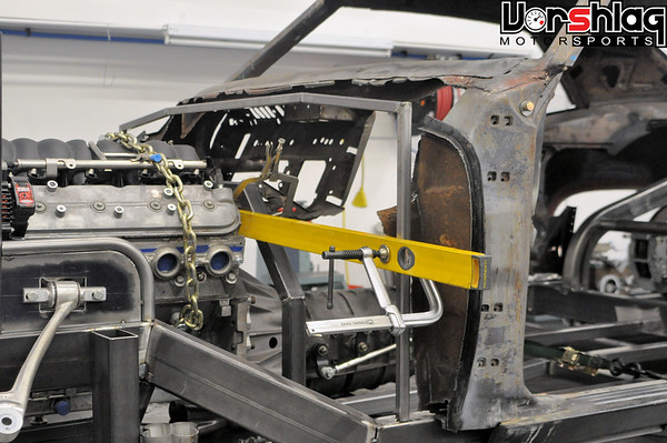
Once the new firewall location was picked (after moving the engine rearwards significantly from the OEM placement) a basic framework for the firewall mount for the steering column / bearing was built. The placement of the steering rack was fairly obvious, and the seat mock-up in the last installment showed where the steering wheel needed to end up... connect the dots and that's where the firewall mount for the column needed to be.


Ryan selected a Sweet Manufacturing steering column cage mount clamp kit, which he modified for better strength. This might not be the final clamp we use for the steering column. For now it lets us quickly rotate, raise/lower, and alter the angle of the column to make the final seating arrangement and steering wheel location/angle perfect.


This clamp was completed after parts of the cage (below) were in place - namely, the horizontal "dash bar". Looking from the engine bay you can see that the angle on the bearing/U-joint at the firewall junction was minimized.

BODY & FRAME STRUCTURE WORK


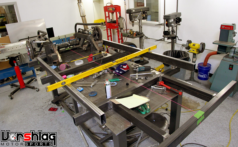
Squaring the body on the chassis was done to ensure the cage layout would be correct and the final body lines would look symmetrical. This took some time, measurements, tweaking, and adjustments.


Some temporary support tubes were added to the window and door frames to add strength while interior panels were cut away piece by piece. We just need the outer skin - everything else is just dead weight that will get in the way of the cage tubes. The final cage structure will add significant rigidity to the overall chassis, so most of the old unibody structure no longer provides meaningful stiffness to a tube framed chassis like this.


These rectangular gussets were added diagonally to join the middle frame and rear frame rails to make the cage layout and load paths work better. The width of the 345mm rear tires pushed the rear frame rails inboard more than you'd normally see on a car like this, so these diagonals help reinforce that offset step in the chassis.

ROLL CAGE COSTS

Building a roll cage for a road course car is a complicated, time consuming job. You have to know the class/rules it is being built for, the construction has to follow the constraints of the chassis you are building it for, there are materials to know how to select correctly and welding techniques to use for various tube and plate junctions. It takes a good bit of skill/experience/technique, proper tools and welders, and when done properly it takes a lot of time.


Lots of people ask us for roll cage quotes, and we usually use $6000 as a starting price for a typical road race cage. That might seem high to some, but even that price rarely covers the materials and our hourly rate. Most times we have to eat about 30-40% of the hours on a fixed bid cage job. Of course some cages cost more, but that's our typical cage cost. I've had trouble explaining the costs to people on the phone so I made a detailed entry about cage costs on our forum and just send them this link. That post serves as a "tech article" to show why our cages might cost more than others', shows some details on a number of different cage jobs for differing racing classes, etc. Other shop owners have linked to this forum post to help justify their own cage costs - more power to 'em.

ROLL CAGE WORK BEGINS

I sent that forum post about cages to the 69 Camaro owner as an explanation, early on during our quoting process. And on a build like this, a $5000 cage isn't a huge impact on the bottom line. OK, so where were we? After the main portion of the frame was laid out on the frame table, and the front and rear subframes created and welded to that, the rest of the body went on...


After the body was on the frame, and the first driver's racing seat was in place, Ryan started laying out the roll cage. Jason and I had some initial layout and classing/rules input, but once he got the inner panels out of the way, Ryan went to town and did his thing.


This is a major step in the overall '69 Camaro build, and Ryan was bending, cutting and notching tubes for two weeks on the main portion of the roll cage structure.


The cage tubes are laid out, measured, and bent carefully. Templates are made, strings are run, angles are measured and it is all transferred into tubing. The notching for each tube junction requires math, templates, the right tools, and careful fitting.


It is easy to have a tube droop or rotate slightly in the bender and have the angle thrown off. Ryan sets up guide tubes (see above) to keep the sometimes 10 foot long tubes from slipping or bending downward in the bender, and watches the digital angle finder attached to the tube during each pull.


Accurate measuring, calculation and fitting is key when building a cage that fits this tight to the chassis and body. Here Ryan is adding some tubing that will make up the floor structure and trans tunnel, which I will show in another post.

continued below
Reply With Quote
Reply

Thread Tools
Display Modes

Posting Rules
You may not post new threads
You may not post replies
You may not post attachments
You may not edit your posts

BB code is On
Smilies are On
[IMG] code is On
HTML code is Off

Forum Jump


All times are GMT -7. The time now is 02:51 AM.


Powered by vBulletin® Version 3.8.11
Copyright ©2000 - 2025, vBulletin Solutions Inc.
Copyright Lateral-g.net