|
|

12-31-2015, 09:02 AM
|
|
Senior Member
|
|
Join Date: Mar 2014
Location: Plano, TX
Posts: 160
Thanks: 6
Thanked 67 Times in 33 Posts
|
|

continued from above

The image above was where work stopped on July 14th, which was when the cage was about halfway finished. There will be additional tubes joining the upper side bars to the main hoop, in the roof, and of course the dash bar and door bars.

All outer tubes are routed very close to the outer skin of the body for maximum room to the driver's helmet and arms.

Now we probably could have argued for not using the optional "FIA bar" (below) on this Camaro. The FIA bar is the vertical bar that goes from the upper corners of the windshield to the foot of the forward most vertical cage bar at the A-pillar. Adding these is just good insurance, and has become common practice in all rally and many road racing safety cages these days.

This is a more critical tube on a more "laid back" modern windshield - which have typically windshields at 25-30° from horizontal (measured on cars in the shop to check this). This 1969 Camaro A-pillar is sitting more upright at a 41° angle, but that still means the top of the windshield/roof is 15-1/2" further back than the base of the windshield and the front foot of most cage tubes, so the FIA bar was added. In a roll over situation this will help keep the roof from crushing - and that's a big part of what a "roll" cage is supposed to do.

The first roof diagonal bar is in place above. Bends were added at the ends to gain more headroom for the driver and passenger. This bar is almost touching the roof skin in 2 spots and the ends fit tight to the cage. Most of the original inner roof structure has been removed except the forward most panel at the front/top of the windshield, and even this inner panel was tweaked for more room.

Here you can see that the second roof bar was added. This is optional, but worth it on a car that will sometimes have two people in it and driven hard on track. The first roof diagonal joins several others in a big "node" behind the driver's head for maximum strength nearest his helmet. These tubes are only tacked in place, and will be disassembled for final welding. Each tube will be individually welded at to the node - one tube at a time on atop the other - for full 360° welds on each tube at this junction.
WOODWARD RACK IS HERE
At this point we are well into July work. This is not the only car Ryan was working on in June/July, as he was pulled away to tackle some final work on the FR-S LS1 car before it left our shop, as well as some work on the LS1 Miata, but the Camaro was his main priority.

The Fox Mustang factory steering rack looked a lot worse for wear, and the original placement left a lot to be desired (it was going to have massive bump steer where it was placed, plus it was in the way of the harmonic balancer). We explained the rack's limitations and suggested a few options to the car owner. Options ranged from electric steering assist to several options of OEM and custom servo-style racks like this made-to-order Woodward rack, below.

He picked the Woodward servo rack, so we sent our calculated dimensions to Woodward and had it built. Brad took this picture of the rack and various parts that came in this kit. Ryan wanted to mount the rack to the front crossmember immediately, but the tailstock on our manual lathe broke, and he needed the lathe to make some of the mounting components, so that had to wait until we repaired the lathe. Next time.
DRY SUMP TANK MOUNTING
Mounting locations for the dry sump oil settling tank was discussed within our crew. Some racing engineers want to use the tank plus the 8-12 quarts of oil it holds as ballast, and place it way in the back of the chassis. Engine builders want this tank want it as close to the engine as possible to reduce/oil feed suction problems to the dry sump pressure pump.
 
With as far back as we have moved the engine and transmission, plus the driver, we felt we are going to be doing pretty well on rear weight bias and went with the forward tank location. This tank is sitting behind where the stock firewall would be, but it will be tucked inside its own (accessible) metal enclosure away from the passenger cabin. The passenger seat is moved back the same ~18" as the driver's side, so their feet will have plenty of room away from this tank enclosure.

Ryan mounted the tank at this point to route the extra forward cage tubes from the roll cage to the vertical tube that ties into the front suspension mounting tubes/plate. You can see the pink layout string in the image above, which runs above the tank. Planning ahead is crucial so we don't have to back track later.
continued below

|
12-31-2015, 09:03 AM
|
|
Senior Member
|
|
Join Date: Mar 2014
Location: Plano, TX
Posts: 160
Thanks: 6
Thanked 67 Times in 33 Posts
|
|
continued from above
TRANSMISSION CROSSMEMBER AND MOUNT
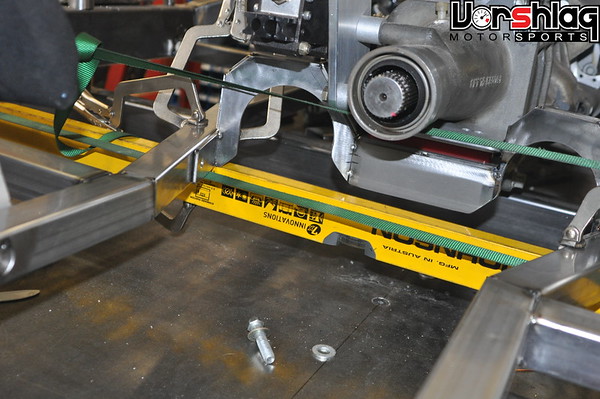
The transmission had been set at the right downward driveline angle, opposite that of the rear axle flange, so that the U-joints are in sync. It had been sitting on a temporary piece of steel clamped to the frame, but now was time to construct the transmission crossmember and mount.

The bottom of this car is going to be flat (for aerodynamic reasons), so the exhaust and driveshaft have to be tucked up well inside the transmission tunnel. That's why the tunnel is so large. Since this is a dry sump motor, the oil pan is short and the transmission sits very low in the chassis. This means the transmission crossmember had to sit low but ALSO have clearance for two 3" diameter exhaust tubes - which made for a fairly elaborate 3D plate structure.
The red bushing sandwiched between the transmission and the crossmember is our 95A polyurethane rubber transmission mount busing we use on many of our LS1/T56 drivetrain swap kits. We have these molded to our specs and this bushing keeps vibration to a minimum while eliminating slop normally seen in an OEM rubber transmission mount. I will show more of this in a later post, when it is out of the car for final welding.
DOOR MOCK-UP + MORE CAGE PROGRESS

Next up in the build was the initial fitting of the fiberglass doors to the car. To save weight the doors are composite and the front sheet metal is aluminum - the only steel skin will be the roof, rear fenders and rear panel.

Mocking up the doors at this point was necessary to be able to lay out the "NASCAR" style door bars for the roll cage.

The car came in with a cage that had a flat "X" bar that was a bolt-in portion (drag racer style - not allowed in road racing). This put the bars inboard of the stock door structures, and made for a very tight cockpit.

The right side lower door bar was fitted first. As you can see above, this bar comes way out into where the shell of the stock doors would be. The amount of interior space gained with the new set-up is dramatic. 8-10 inches of additional room is available on each side.

Fitting bars like this was tricky and took lots of iterative measuring and small cuts for tubing clearance on the rear door jamb. But it is worth it in the end, and the driver and passenger will both have plenty of elbow room and additional side impact crush space inside the cabin.
 WHAT'S NEXT?
At this point it is around July 28th, and the cage was mostly done - now we just need to have the customer stop by for a "fitting". This is where he chooses the final seat among the 3 he provided as well as a half dozen other options we had at the shop. He finalized the seat placement and angle so we can add the harness bar. This test fitting also allowed us to position the shifter and final steering wheel placement.

Once we knew all of that Ryan will finish the horizontal door bars and the verticals that tie those into the frame and together. The car owner flew in July 31st for the fitting, so I will show that next time.

There's more to show on the 69 Camaro next time - front suspension work, custom exhaust headers, new floor mounted pedal arrangement, exhaust layout and component discussions, steering rack mounting, steering shaft construction, and more. I'll try to get another post written about this car in the next couple of weeks.
Thanks for reading,
__________________
Terry Fair @ Vorshlag Motorsports
|
12-31-2015, 09:09 AM
|
|
Senior Member
|
|
Join Date: Mar 2014
Location: Plano, TX
Posts: 160
Thanks: 6
Thanked 67 Times in 33 Posts
|
|
Project Update October 20th, 2015: This forum post update covers much of the work we did in August of 2015 to the 69 Camaro project, which included custom exhaust header fabrication and some front suspension work.
CAGE FITTING WITH OWNER
The owner flew in July 31st to check out the build in person and to sit in a couple of different seats in the car.

First up was the aluminum NASCAR Lajoie seat he had purchased before the car came to our shop. This is a full containment style seat with a separate head rest section, but a weird seating angle. It is a really well made seat and looks like a work of art. While these seats are more commonly seen in circle track cars we made it work for this road course sedan.

Next up was a Sparco composite FIA seat he had purchased for the passenger side, which Ryan mocked up on the driver's side. It looks more comfortable but doesn't have the head containment portion - which is fine for most HPDE and Time Trial cars. We're all still discussing which seat is right and will leave room for both in the final build, but both of them are moved 18" rearward for this build - to mimic the engine & transmission setback - both of which will help move mass to the rear axle from the front. We are still shooting for a slight rear weight bias in the final build.

The Tilton pedal box and a temporary mock-up of the remote shifter for the G-Force transmission was tested with the owner sitting in both seats, as well as the steering column and wheel. This helped us nail down the location for all of these driver controls as well as door bars for the driver's side. Helmet clearance to the cage is exceptional.

Although he was only here a few hours, the car owner Stewart was happy to see the work in person for the first time since he dropped the car off. Of course he gets detailed emails with these same images I'm showing in this build thread and more, plus we have some good questions from him we have to answer from time to time. There is also a lot of feedback and direction he gives us on what he wants things to look like and functional aspects, all of which we incorporate into the build.
 CUSTOM EXHAUST HEADERS - RIGHT BANK
At this point the drivetrain is in its final location, set back behind the OEM firewall location, with the corresponding driver setback. The new frame is in place and the front frame rails are narrower than before.

Of course there's no off-the-shelf, full length exhaust header appropriate for this rear-biased LS3 in a 69 Camaro with a custom frame like this, so it was time to fabricate custom headers.

It is often a rushed part of any big build, but we waited until all of the items were in place before starting the header fabrication. This is why the steering column was already in, the front frame was done, the dry sump tank, much of the firewall and tunnel structure laid out, and a mock-up driveshaft was in place.

We use 304SS mandrel bends in the same bend radius as our Ice Engine Works header modeling kit. Each tube was laid out in the snap-together plastic bends, then one tube at a time was turned into stainless bends cut and tack welded together.

The passenger side header was tackled first and it came together in under 2 days. Later in the build each header will come off and be final welded.

These slip-fit bolt-together collectors were used on these 1.75" diameter long primaries. They have excellent craftsmanship and were supplied with the build.

Its a snug fit in there but the headers have plenty of room to the frame rails, dry sump tank, and are above the bottom of the floorpan, as this will be a flat bottomed car.

A section of 3" exhaust tubing will run down the from the right side, cross under the tailshaft, and then stack top-to-bottom with the left side 3" exhaust tube and run inside the tunnel. A crossover merge will be built in the tunnel, but that's for another day.
CUSTOM PEDAL MOUNTING
Now that the passenger side header was completed the driver's side still needed some parts in place before it could begin.

The new bottom-mount Tilton pedal assembly was mounted. Some components from the "top hung" pedal assembly that came with the car were re-used on this "bottom-mount" assembly.

Ryan added structure and tweaked the floor section there to make room for these pedals.
FRONT SUSPENSION WORK
Now that our manual lathe was back up and running the weld-in bungs could be machined to mount the steering rack and servo.

These are mild steel bungs of bar that are machined inside and out to perfectly fit the bolt needed and the tubing that these will attach to. Simple things that fabricators need to whittle out from time to time.
continued below
|
12-31-2015, 09:11 AM
|
|
Senior Member
|
|
Join Date: Mar 2014
Location: Plano, TX
Posts: 160
Thanks: 6
Thanked 67 Times in 33 Posts
|
|
continued from above

Some mounting bungs were also machined for the transmission crossmember, and then those were tacked to the frame for a proper crossmember mount.

The holes were drilled in the square tubular front subframe to mount the weld-in bungs. More structure is going to tie all of the subframe together at a later day, and it won't be left "open ended" like this.

A look from underneath shows the mounting bungs tack welded in place and the new Woodward steering rack finally mounted to the chassis. From here it was time to make the steering shaft, or at least mock-up most of it, before header tubes were snaked around that.

Another one of Brad's "glamour shots" of the rack mounted in place. I've never seen a steering rack that looked so damned good. Weird.

I snapped a quick and ugly shot here to show that the valve covers were installed an an ignition coil and spark plug wire were in place. This coil and plug wire was moved from port to port to make sure each primary tube gave clearance for the plug wire.
CUSTOM EXHAUST HEADERS - LEFT BANK
Now that the steering rack was in place, and the steering shaft built (and attached at one end) and mocked in place, the driver's side exhaust header could be laid out and built.

Back to the Ice Engine Works kit, which was mocked-up up on the exhaust flange. Several iterations of each primary tube could be quickly tested before cutting any metal.

Once the routing looked good in plastic each Ice tube model can be removed and replicated in stainless steel bends. Lots of time but its worth it for one-off or prototype header development.

Snaking around the steering shaft is always tricky, so the driver's side header on LHD cars usually takes a bit more time. The steering shaft is a 2-piece collapsing design using stainless 3/4" DD inner bar that slides inside 1" hollow DD tubing, with Flaming River needle bearing U-joints at both ends.

At this point all of the ignition coils and plug wires were attached to verify primary room and most of the tubing layout is complete. In the image below you can see the convoluted design of the transmission crossmember, which is necessary due to the very low mounting height of the engine (dry sump oil pan) and transmission, flat bottom nature of the floorpan, and the need to tuck two 3" main exhaust pipes above the floor.

The starter is in place here and you can see how the collectors come back into the custom transmission tunnel. The driver's side was the constraint on primary length, as the external shifter has levers and rods that reduce clearance on that side. The shortest primary is about 26" long, which will is appropriate for this motor, and still considered full length.
RADIATOR MOUNTING
To check hood and sheet metal clearances the entire front end was installed again.

The customer brought us a custom C&R Radiator made to bolt into a 69 Camaro. It was a beautiful 2-pass heat exchanger that had an integral oil cooler and power steering cooler and included a plastic fan shroud . This would be a great package for a street driven car, but this is more of a track beast.

The other problem is the C&R that the owner provided (above left) was too wide to fit the frame rail width on the new custom frame. The width of the new frame was dictated by other factors (wheel size/offset, C6 spindles, C6 control arms, camber range needed) so this nice C&R radiator would have to be changed. We used the Griffin (above right) stock car style radiator that would soon go into my C4 Corvette (Project #DangerZone) as a mock-up for the 69 Camaro.
continued below
|
12-31-2015, 09:12 AM
|
|
Senior Member
|
|
Join Date: Mar 2014
Location: Plano, TX
Posts: 160
Thanks: 6
Thanked 67 Times in 33 Posts
|
|
continued from above

The narrower width of the Griffin worked perfectly. We had a ducted hood and custom front grill inlet idea already in mind so a severely forward canted radiator angle was what was tested. With this data another "basic" C&R Radiator was ordered, this time without the integral oil and power steering coolers.

Once the new C&R arrived Ryan began to build the brackets necessary to mount it to the frame. Some of this is square tubing, the rest is flat sheet with dimple die holes to give it strength and reduce mass.

The tubular front mounting bar for the splitter and nose was also built, but I will talk more about that next time. Here you can see the new C&R radiator in its final mounting location and tilt. Since it is sitting this low we will be able to block off the upper grill completely (reducing drag) and make a inlet duct box for the lower grill to feed the various heat exchangers, which will then vent out of the hood. This C&R core has a -20 AN fitting for the upper hose connection, which you can see above. The lower "hose nipple" would later be cut off and another -20 AN male fitting welded in place. This car will have all pressurized systems plumbed with threaded fittings, throughout, even coolant lines.

It is always a good idea to protect the fins of the heat exchangers during fabrication. We wrap card board around them to prevent damage to the delicate fins when these go in and out, get mocked up in various ways, etc. You might see a sneak peak of a splined 3-piece swaybar in the images above, but I'll talk about that more later, when the splined ends and endlinks are fitted.
CUSTOM DRIVESHAFT
The custom 3.5" aluminum driveshaft was spec'd out by Jason and Ryan and ordered a week earlier.

After that arrived it was slid in place to the output shaft of the G-Force trans and bolted to the axle flange on the Ford 9" input flange. It fit perfectly and looked great, and we've ordered more shafts from this supplier since.
 WHAT'S NEXT?
More fabrication was completed and more parts were ordered and/or installed in September including more front tubing and structure, custom accessory brackets, and more.

And in October we're working on front grill/bumper, custom aero with a dual plane splitter, custom front sheet metal and flares/canards, front brake ducting, additional heat exchangers, and hood ducting.

Until next time,
__________________
Terry Fair @ Vorshlag Motorsports
|
12-31-2015, 09:13 AM
|
|
Senior Member
|
|
Join Date: Mar 2014
Location: Plano, TX
Posts: 160
Thanks: 6
Thanked 67 Times in 33 Posts
|
|
Project Update December 6th, 2015: This forum post update covers work we did to the 69 Camaro in September of 2015. This included LED tail light fitting, radiator work, cooling fan mounting, custom splined swaybar mounting, as well as custom engine accessory drive brackets that had to be designed and fabricated. This chunk of 69 Camaro work was all done in a VERY busy month for Vorshlag's race shop, too.
LED TAIL LIGHT INSTALL
The original tail light assemblies were 46 years old, worn, and showing their age (see below). These were made for old style incandescent light bulbs and the owner wanted something that looked original but had a more modern function underneath - which is pretty much the theme of this whole build, so its natural that this thinking went into the lighting as well. Since this car could be made legal for limited road use. Also, street legality makes it possible to attend events like Optima and possibly even run in SCCA's CAM class, so it needs to have functional head lights, brake lights, turn signals and wipers. That aside, it needs to at least have brake lights for any track events.

These "little street car things" can be time consuming additional work to high end, tube framed, serious aero, race car build like this, but its nothing we cannot tackle. Texas has a rolling 25 year exemption for annual emission inspection, so a 46 year old car like this can be inspected and road legal for a mere $14 "safety only" inspection - where they check the horn, lights, and turn signals only. Next year this exemption applies up to the 1992 model year (aka: now a 1992 model car is a "Classic"), which gives me some evil ideas on another car I own (many of you will figure out what and why, quickly).

We made our $2011 GRM Challenge winning race car (above and below) pass the Texas safety inspection checks with only a few small changes, as it was a 1986 model when we did this back in 2012. Amber LED turn signal strips were added up front, since the E36 grafted nose didn't have room for the OEM housings. After it got the legit inspection and registration stickers (and insurance) I drove it to Cars & Coffee type events (on "DOT legal" Hoosiers) without the need to trailer it.
And for those that doubt that an LS-powered RWD car with an OEM tub can be built with big wheels and tires (18x11) and still hit the 2500 pound goal we have guesstimated for this 69 Camaro, well this was our all OEM steel and glass equipped, wide bodied BMW E30 with an aluminum LS V8 on the scales at 2534 pounds, 100% street legal. Granted, this only had a 4-point roll bar, but it had a full interior and dash. And please ignore the fit and finish on that thing - it was built for $2010 in parts for the GRM event (the 18x11 CCWs and ASTs we sold it with were outside of that budget).

This Camaro is pretty overbuilt compared to this E30, so it might be as much as 100-200 pounds heavier, but also has all aluminum front bodywork, fiberglass doors, and most of the unibody structure is gone. It won't be some 3300 pound, pavement crushing Pro Tourer, trust me. We will weigh the heck out of this car when its off the frame table (soon!).

So the 69 Camaro needs functional tail lights, turn signals, and headlights to be street "legal". We discussed a number of options with the owner, including some rather modern looking billet aluminum tail light assemblies with integral LED lighting, like the ones below. But the owner wanted to stay with the classic housings and just use LED lighting underneath, as unobtrusively as possible.

Then we looked at LED retrofit kits for 69 Camaro housings, like the image below, and that's what we all agreed to use. This was coupled with a flasher unit made for LEDs, and the total on these parts was around $250 for a quality brand that had good reviews by users.

Next up was ordering a brand new pair of OEM style 69 Camaro tail light assemblies, then Ryan added the LED lighting arrays to the housings. There is a tedious bit of work involved to do that but he got them installed and wired up to a pair of harness connectors for each housing.

These are mounted in the back panel and ready for wiring, which is still several weeks away. Better than looking at two holes in the rear bodywork.

These look fairly "plain jane" now but when you power them up they are BRIGHT, so that should go well with the LED headlight assemblies as well...

These 7" LED "truck light" style round bulb replacements will replace the $8 stock style round bulbs we have in the car now for mock-up. We will install these later in the build - don't want to damage them, as they cost a bit more than $8 each. 

That's a bit of a sneak peak at where we were in late November and shows the airbox and small tubular bumper mounting structure used to mount the splitter struts, headlights, fenders, and more. We'll get to that further in this thread.
continued below
|
12-31-2015, 09:15 AM
|
|
Senior Member
|
|
Join Date: Mar 2014
Location: Plano, TX
Posts: 160
Thanks: 6
Thanked 67 Times in 33 Posts
|
|
continued from above
RADIATOR OUTLET FABRICATION
This is one of those projects where plumbing becomes critical, as the motor has a dry sump and we're adding oil coolers for the engine, power steering, and more. When we build any race car plumbing we go to AN style (37° inverted flare) fittings and the appropriate lines for the pressure and fluid being used.

The C&R radiator we spec'd to fit the frame rail width and height we needed at the layback angle we wanted was available with a -20 AN fitting welded to the upper (inlet) hose connection. But the lower (outlet) was a normal nipple made for a clamped rubber hose fitting.

The C&R's lower hose nipple was cut off and shortened, then an additional ARP -20 AN aluminum weld bung was sourced, mocked-up, and welded in place for the lower outlet.

A billet thermostat housing was added to the water pump outlet in a matching -20 AN size. We still need to adapt the upper radiator hose mount at the water pump and the heater hoses, then all of the coolant connections can be matching AN fittings. Is this 100% necessary? No, but it is commonly done on dedicated race cars, which this car has many aspects of.
FAN BRACKETS + SPLINED FRONT SWAYBAR MOUNTING
These two items seem pretty unrelated, but the packaging of the radiator and front swaybar were actually done hand-in-hand, earlier in the build. The placement of the swaybar is limited by several things - like the approach paths for the splined "ends" that attach to endlinks and ultimately the C6 lower front control arms, and often by the crossmember or engine. We had long lost hope for an off-the-shelf one-piece swaybar solution, so as most race builds do we went with a circle-track style splined tubular bar setup.

These come in a variety of lengths, diameters, and stiffnesses - usually too stiff for street car grip levels, but with 315 Hoosier A6 tires up front this car will have plenty of grip for track use. You always hope for there to be plenty of room to mount a straight swaybar like this, and with the 18" setback of the engine we had ample space in front of the engine. But it was apparent that the ducting for the exhaust side of the radiator would be right where the anti-swaybar needed to go. We've seen some kooky placements of swaybars, like at the top of the engine bay with with 30" long endlinks, but we chose to keep the endlinks manageable and the splined ends within reason. So we mounted the swaybar to grease-able bearing mounts shown above.

So with the swaybar mounted the dual fan setup from the existing C&R "bolt-in 69 Camaro radiator/fan combo" were mounted to the new C&R core. Ryan had mocked the fans up before the final location for the swaybar was picked. He made templates for aluminum bracketry in cardboard before transferring it to aluminum sheet.
 You can see above why the fan brackets and swaybar were done at the same time - fighting for space
The aluminum sheet was cut in the sheer and bandsaw, then bent in the brake, then nut-serts were added for the fans housings to bolt to. The finished aluminum brackets were then riveted to the exposed flanges on the C&R radiator, and the fan assembly was then bolted to the new brackets. It all fits tight to the fins (but not touching), leaves little of the radiator core expose beyond the plastic shroud from the fans, and could work well for street use if needed.
With the swaybar location locked down Ryan could then specify the splined aluminum ends to order as well as pick up the end link parts needed to tie the bar into the control arms. I'll show that in a later update, as it was done a couple of weeks later than this.
CUSTOM ACCESSORY BRACKETS
Early on in this build we were all concerned with the brackets used to mount the accessories to this LS3 based dry sump engine. The alternator on the car when it came here was not the OEM LS3 unit, but a smaller aftermarket unit rated at lower amperage. Somebody had also hacked up this "smaller" aftermarket unit beyond recognition - trying to make it fit the OEM bracket and the previous front end. Ryan found a racing style, smaller diameter alternator that was rated at the appropriate amperage so this needed to be mounted to the engine. The power steering pump was mounted to the same OEM cast aluminum bracket that wasn't going to work, so this needed to be re-mounted as well.

We had narrowed the front frame rails by about 2" from the "kit" front end the car came in here with, making space for both of these accessories more of an issue. There wasn't an of off-the-shelf bracket setup we could find that would re-use the various pulleys and engine accessories - including the balancer and dry sump pump drive - without some custom bracketry. We discussed this with the customer before proceeding, and looked at all manner of off-the-shelf LS bracket options, both factory and aftermarket. None seemed to fit the confines of this frame and hood line.
continued below
|
| Thread Tools |
|
|
| Display Modes |
 Hybrid Mode Hybrid Mode
|
 Posting Rules
|
You may not post new threads
You may not post replies
You may not post attachments
You may not edit your posts
HTML code is Off
|
|
|
All times are GMT -7. The time now is 04:10 PM.
|


 Brian Hobaugh SCCA National Tour June 2014
 First Hemi 'Cuda Convertible Ever Built
 Short clips: Goodguys Pleasanton autocross and pit videos


