...

Go Back   Lateral-g Forums > Lateral-G Open Discussions > Project Updates
User Name
Password


Reply
 
Thread Tools Display Modes
  #1  
Old 05-14-2018, 01:01 PM
nickcornilsen's Avatar
nickcornilsen nickcornilsen is offline
Member
 
Join Date: Oct 2011
Location: Roseburg, OR
Posts: 88
Thanks: 0
Thanked 43 Times in 19 Posts
Default

Fall 2011

Now that the front suspension was installed, it was time to begin designing the rear suspension. I decided to start by laying-out the stock control arms, lacking good CAD models.

I bought a slab of granite from a counter top store. Scratch that, I bought three. I blued it up and calibrated it to a certified granit block, found it to be within .005 of flat... the other two were flat at about .020... Just an FYI for those looking fo an inexpensive super-flat surface.


I also digitized the wheel-wells of my car to check wheel fitment.


For a little bit of motivation, I threw a rear-wheel in there after i cut the wheel-wells out.


I decided I needed more accurate data about the geometry of the transmission, so I called up a locale guy who is quite well-known in the pro-touring community to use a CMM arm to measure the parts... we worked something out and I got some very good cad models. So then CAD design commenced:


Reply With Quote
  #2  
Old 05-14-2018, 01:01 PM
nickcornilsen's Avatar
nickcornilsen nickcornilsen is offline
Member
 
Join Date: Oct 2011
Location: Roseburg, OR
Posts: 88
Thanks: 0
Thanked 43 Times in 19 Posts
Default

Fall 2011

I left off on updating this thread about the time I finished designing my rear suspension... some screens shots of the cad files can be seen in my earlier posts.


After design, I went on to waterjet/laser the parts out, and began fabrication:


Gotta love a nice CNC transmission support cross member:


Next up: How to connect the engine and transmission...
Reply With Quote
  #3  
Old 05-14-2018, 01:03 PM
nickcornilsen's Avatar
nickcornilsen nickcornilsen is offline
Member
 
Join Date: Oct 2011
Location: Roseburg, OR
Posts: 88
Thanks: 0
Thanked 43 Times in 19 Posts
Default

Winter 2012 Through Fall 2014
Now I needed to figure out how to connect the engine to the transmission. The OEM solution is the 'torque tube.' there are front engine mounts, a long tube that connects from the bellhousing to the transmission, and transmission rear mounts. initially, I decided not to use this since it is large, and I was worried about interior room. Also, it is too short, and getting a longer shaft that will not vibrate is tough. So, an open shaft seemed the way to go.

Unfortunately, Nobody makes an adapter that goes straight from the clutch to a driveshaft, so I had to design my own. I make castings for a living, so I figured I'd make up a pattern and have it made from aluminum.

Aligning the engine and transmission:


Cad model of the tailhousing casting


Shaft and bearing assm design


Heck I even built it!


The problem is, it is too heavy. I drove a corvette, and it already seems like the syncros had a hard time with the rotating mass of the corvette shaft, let alone mine which is 4 times heavier! At any rate, I didn't like the solution, I was concerned the mounts wouldn't keep the engine in line, and I'd have a hard time lining everything up if I ever pulled the engine. So, I decided to go back to the torque tube.

A local shop had experience lengthing these, so they did it for me. Turns out DriveShaftShop.com can make a shaft that can handle the torque and RPM just fine, so there really is no reason not to use the torque tube. It just required some diligence in making the tunnel tight to the tube, as much as possible.


With the torque tube in hand, mounting the shifter and installing the linkage went quickly, as did installing the tunnel:


Last edited by nickcornilsen; 02-19-2024 at 02:04 PM.
Reply With Quote
  #4  
Old 05-14-2018, 01:04 PM
nickcornilsen's Avatar
nickcornilsen nickcornilsen is offline
Member
 
Join Date: Oct 2011
Location: Roseburg, OR
Posts: 88
Thanks: 0
Thanked 43 Times in 19 Posts
Default

Fall 2015 Through Spring 2017

More progress has been made!


With the transmission tunnel installed, I attached the upper suspension mounts:


I wish I'd taken more photos... but that's the rear suspension mocked up. Now, wheel wells begin:


I did the exhaust before I removed the transmission for working on the wheel wells, but this is a pic of it installed. It fits snug, but I can remove it all fairly easily.


Fuel cell Mount
I bought a summit fuel cell, 15 gallon with the little sump, and a gauge. To make the transmission removable, I need to be able to drop the cell out easily. Here's what I came up with, after a little Coffee and CAD:


Next, I'm going to finish mounting the fuel cell, then I'll build the straps to retain it.

Last edited by nickcornilsen; 02-19-2024 at 02:05 PM.
Reply With Quote
  #5  
Old 05-14-2018, 01:05 PM
nickcornilsen's Avatar
nickcornilsen nickcornilsen is offline
Member
 
Join Date: Oct 2011
Location: Roseburg, OR
Posts: 88
Thanks: 0
Thanked 43 Times in 19 Posts
Default

Summer 2017

Here Goes again!

Between now and the last time I posted, I did manage to finish the fuel cell mounts, and even primered the back-half of the car's frame, wheel-wells, and suspension mounts. I did not, however get pictures... and I proceeded to stack parts and materials into the trunk of the car, meaning I won't be getting better pics for a while.


After primer, I got a bit distracted from the car for the summer. Barn parties, house projects, and even some track time in my Chumpcar racer stopped progress from July 15th until about 3 weeks ago.


Anyway, I've been busy though!

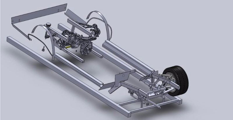
I decided to transition to the front of the car. There's alot of reasons for this, but mainly it comes down to poor design of my chassis jig... I can't get under the car if the floorboards are in!

The first step was working on the driver's position, pedals, and steering column.

I bought a column from a '96 camaro. I transferred the Nova columb brackets to it, and shortened it. There's enough info on how to do that out there, that I won't go into it. It's not to hard though.

I realized I was going to have to decide on an exhaust system. After some research, I decided it was either custom headers, or modify some LS7 manifolds.
LS7 manifolds are nice, the have a dual layer, and make really good power.
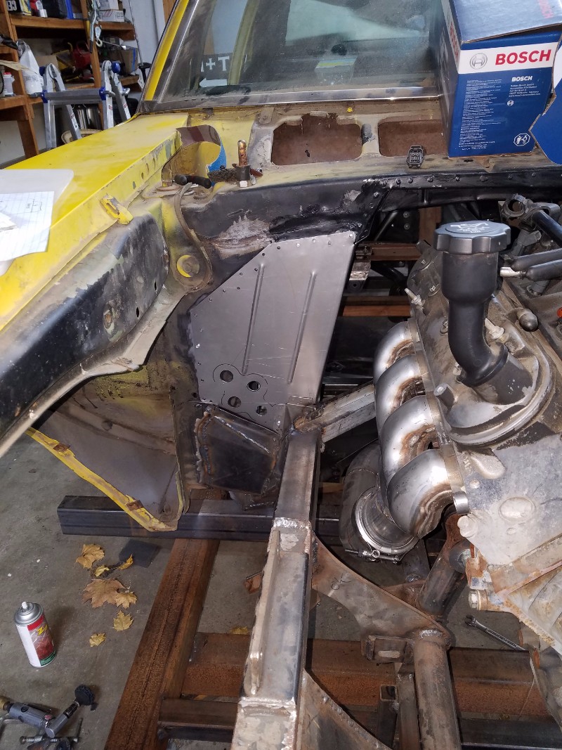
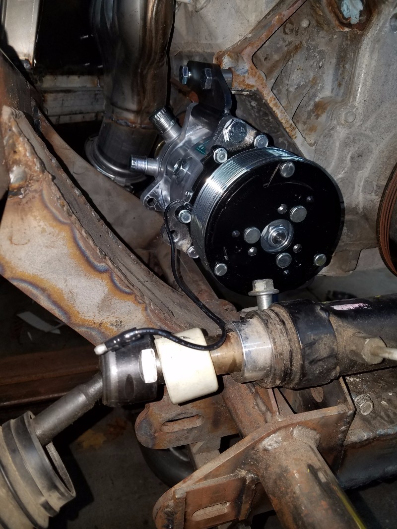
I purchased a pair, and cut the flanges off. You can see below, I have alot of room for the steering linkage.


The picture below shows the clutch and brake pedals installed. While trying to fit the column and pedals, I found that some of the frame tubes I'd installed back in 2012 would not work, as they took too much of my footwell. I also found out that there was no way to get an exhaust pipe through on the driver side.


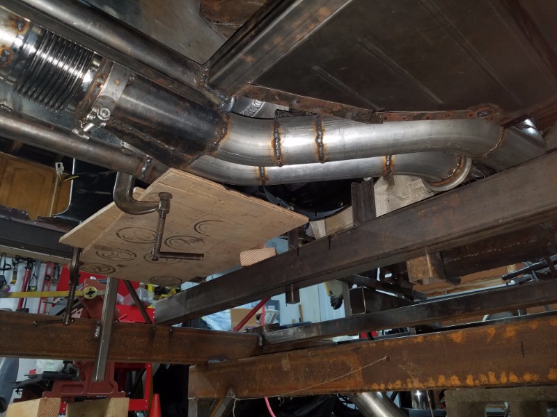
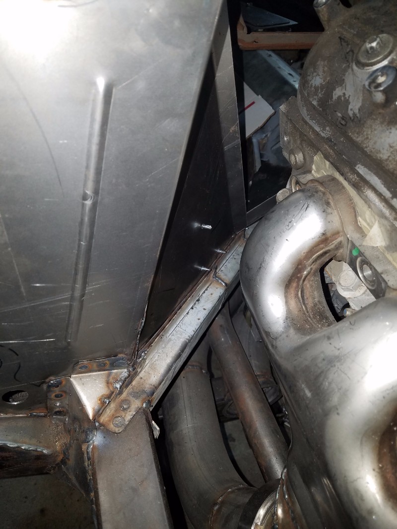
Now that I'd determined the stock pedal assembly would work, and that I'd have to hack up the frame a little bit, I dove into the exhaust. You can see below what I THOUGHT I'd do for exhaust.


To prevent any extra encroachment into the passenger footwell, and to allow room for an AC evaporator, it worked best to route two 3" pipes next to eachother, and to join then under the torque tube. I set out to modify the manifolds, and re-did the frame tubes in the area to make room.


Last edited by nickcornilsen; 02-19-2024 at 02:06 PM.
Reply With Quote
  #6  
Old 05-14-2018, 01:06 PM
nickcornilsen's Avatar
nickcornilsen nickcornilsen is offline
Member
 
Join Date: Oct 2011
Location: Roseburg, OR
Posts: 88
Thanks: 0
Thanked 43 Times in 19 Posts
Default

Winter 2017

Once the exhaust was done, I purchased my Vintage Air kit, test fit it, and built the passenger size footwells.


I figured i'd better check and make sure my AC kit would fit. I wanted a low mount one. It fits, quite snugly!


So, back to the pedals.

I needed to make a bracket to test the location of the gaspedal. It wasn't working to test the pedal placement without the pedals returning, so I rigged up some springs.


Now, I'm not a guy who invents the wheel when he doesn't have to. So I borrowed heavily from RomanCommander's build, and used the same bracket, booster, and clutch master he did.


Reply With Quote
  #7  
Old 05-14-2018, 01:07 PM
nickcornilsen's Avatar
nickcornilsen nickcornilsen is offline
Member
 
Join Date: Oct 2011
Location: Roseburg, OR
Posts: 88
Thanks: 0
Thanked 43 Times in 19 Posts
Default

Winter 2017

More progress made!


This shows my AC unit installed under the dash, as well as the access plate for the top of the torque tube. That will be how I bleed the clutch.


Firewall Completed! This took alot of fidding, and thinking everything through. I had to buy and install the throttle cables to make that work, install the pedal assembly, and so on. I wish I didn't have to make such a patchwork, but to get everything to fit, and given my tooling limitations, I did the best I could.


3 Coats of Southern Polyurethane Epoxy!

The next phase of this project is to finish the core support, inner fenders, steering linkage, and swaybars.


Core support installed.


Motor placed, radiator just set in for reference. Lots of room for a fan! You can see the downbars, and swaybar tube mounted. the C5 bar is too wide, given that I narrowed the suspension up by 4 inches. I bought a speedway Engineering hollow tube, and pillow blocks.
Reply With Quote
Reply

Thread Tools
Display Modes

Posting Rules
You may not post new threads
You may not post replies
You may not post attachments
You may not edit your posts

BB code is On
Smilies are On
[IMG] code is On
HTML code is Off

Forum Jump


All times are GMT -7. The time now is 07:59 PM.


Powered by vBulletin® Version 3.8.11
Copyright ©2000 - 2026, vBulletin Solutions Inc.
Copyright Lateral-g.net