...

Go Back   Lateral-g Forums > Lateral-G Open Discussions > Project Updates
User Name
Password


Reply
 
Thread Tools Display Modes
  #111  
Old 06-05-2009, 09:53 PM
Damn True's Avatar
Damn True Damn True is offline
Senior Member
 
Join Date: Sep 2005
Location: San Jose, CA
Posts: 795
Thanks: 0
Thanked 0 Times in 0 Posts
Default

Been putting off this task for too long. Time to get after that damned undercoating. Mercy sakes this is a miserable job! The best (worst) part is that when the car is done, nobody will ever, ever say, "Gee, you did a really nice job removing the old undercoating. Completely thankless labor.

I'd scraped for a while and swept the floor when the debris got too messy twice before I took this photo. This is the third cycle of mess from the fourth circle of hell. Nothing but a heat gun, various scrapers and a wire wheel......and beer......and the Giants on the radio.


Looking from the drivers side rear toward the front. I left the bottom of the trunk pan alone, that'll be cut out. The dark bits forward of the back seatbelt mounts are just grease/dirt. That'll come off with simple green


I made it to the front seatbelt mounts and had to stop.


I hope to finish the scraping tomorrow and start with the de-greasing. I have a plan in mind for that. Not sure if it'll work. Good thing the wife will be away. It's going to be messy.
Reply With Quote
  #112  
Old 06-06-2009, 04:00 AM
Rick Dorion's Avatar
Rick Dorion Rick Dorion is offline
Senior Member
 
Join Date: Jul 2004
Location: Accord, NY
Posts: 587
Thanks: 0
Thanked 1 Time in 1 Post
Default

I used a heat gun and scrapers too. Then I went back and would warm up a small area I wanted to finish and use a rag with mineral spirits. Too many hours though! Nice progress.
__________________
69 Camaro therapy program, 410, M22! SOLD
68 Camaro - SOLD
67 Bel Air - Hmmm.
Reply With Quote
  #113  
Old 06-12-2009, 10:48 AM
Damn True's Avatar
Damn True Damn True is offline
Senior Member
 
Join Date: Sep 2005
Location: San Jose, CA
Posts: 795
Thanks: 0
Thanked 0 Times in 0 Posts
Default

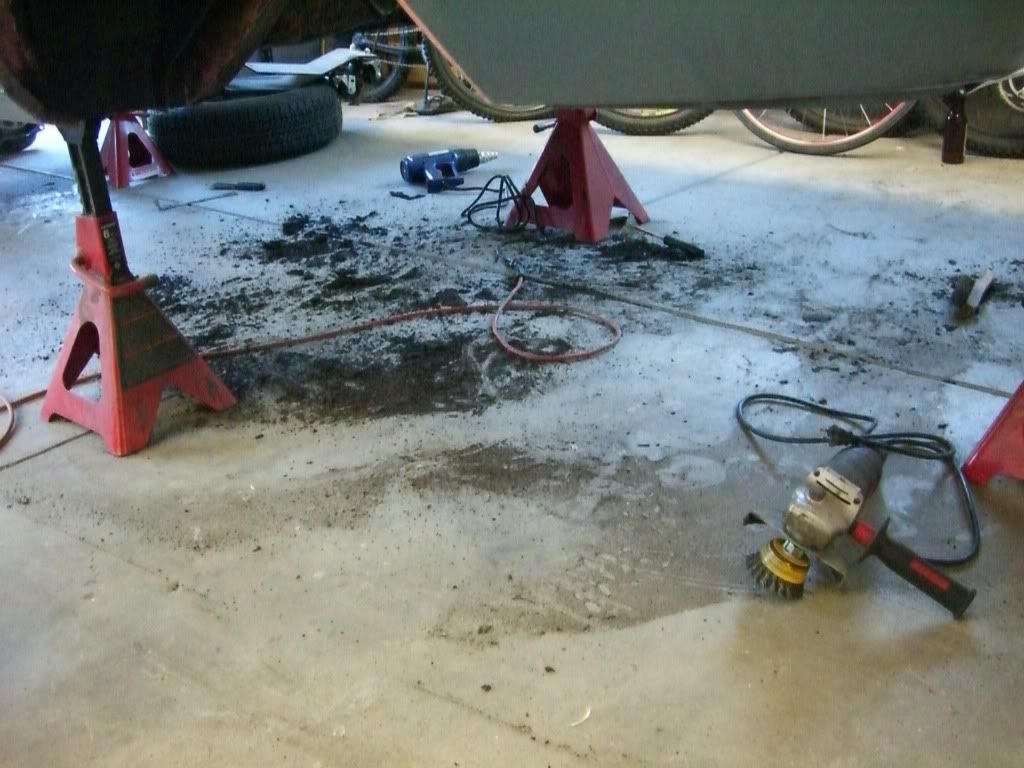
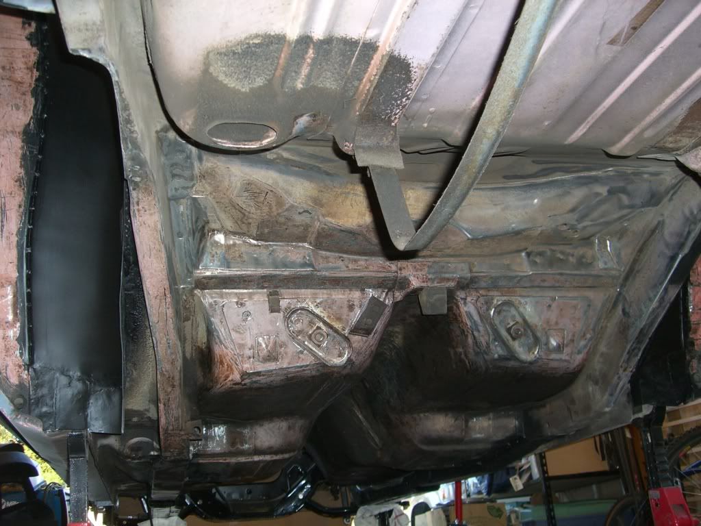
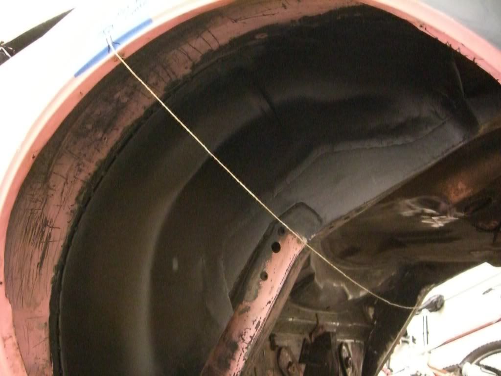
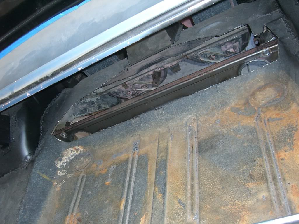
Well, I finally got all the undercoat scraped of the bottom of the car. What a horrible job that was. My garage floor is a wreck!

With that done, though I had time to work a bit on the assembly of the steering system last night.

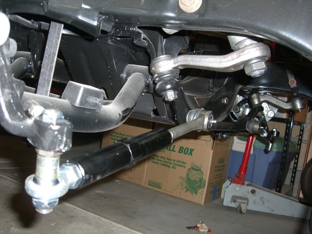
Started with the idler arm and steering box. Found out from David Pozzi that there can be some bind with the idler if the drag link is not installed with the idler arm/subframe bolts loose. He's right. I didn't loosen the bolts before I put the drag link in and....Yup. Sure enough. Bound up like a colon full of cheddar cheese.

Not to self and anyone else with a Camaro: David Pozzi knows his stuff. Listen to him.


The steering box is an ATS 670 unit. These are built for ATS by Tom Lee. I've had the pleasure of speaking to him on the phone. He struck me as one of those eccentric old wizards. When he isn't building super high-zoot stuff for teams in NASCAR, ALMS and others he works on stuff like this for us mortals.

The ATS/LEE 670 boxes are initially built on an assembly line with normal production tolerances. ATS's spec for the Lee box requires that every brand new unit is completely taken apart, re-honed, blueprinted, re-valved, dyno tested, magna-fluxed, and finished in some kind plating. They used to use a really sexy looking cadmium, but the CA EPA (nazis) rules are such that they are now using zinc. Still a good looking unit, but not as cool as the cad plating. These are race proven precision boxes, built exclusively for ATS. I don't know all the details of what Lee does with the valves, but I've driven a car with one of these in it, and it is by far the best feeling recric-ball steering gear I've ever felt. Better than a lot of rack/pinion setups in terms of feel.

Tyler, feel free to expand on this a bit.

Next up is the tie rod assemblies. The inner is a run of the mill Moog unit. The outer though is kinda neat. Baer brakes makes these things called "Baer Trackers" (a bit silly) but cool. Big honkin high offset rod end connected to a 1-3/16" dia aluminum coupler that threads directly onto the inner tie rod. The Baer Trackers provide the capability to adjust out any remaining bump-steer from the system by swapping the cad-plated shims (see photo) either above or below (or both in differential amounts) the rod end. A bit bulky, but still lighter than the traditional tie rod it replaces.


So with those bits installed I can see about mocking up some of my clearances.


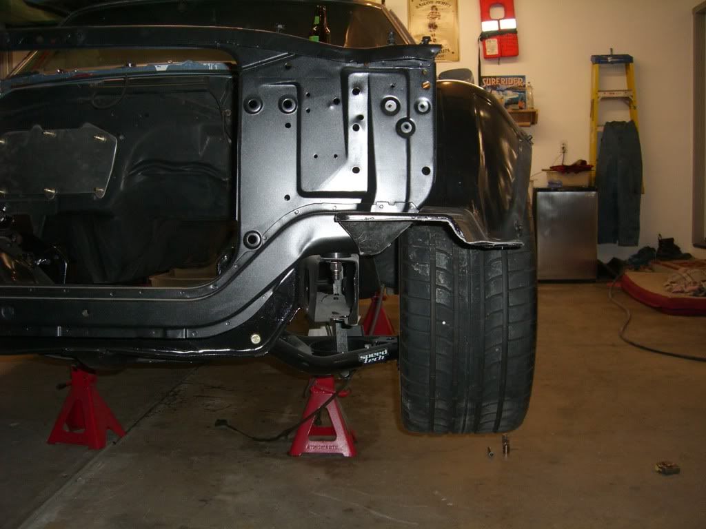
That's a 275x40x17 tire on a borrowed 17x9 vette rim. The offset of the wheel is nothing like what I'm going to run, but it gives me something to calculate from.

....and it looks like I have some "cipherin" to do here.


With the steering arm bolted directly to the spindle, the tie rod assembly set at the OE length and the max offset on the bump steer adjuster the rod end crashes with the inner flange of the wheel.

Spoke with Tyler about it this morning, and the solution is not that big of a deal. I can space the steering arm inboard a bit, shorten the tie rod assembly accordingly, and the wheel spacer I will need to run to clear the Wilwood 6-pot brakes will move the wheel outboard enough to provide the required clearance.

It's always something isn't it?

Not to worry though. With the Speed-Tech control arms adjustable steering stop feature I'll be able to make the above modifications without much negative impact on total available steering angle. SWEET!

Last edited by Damn True; 06-12-2009 at 11:36 AM.
Reply With Quote
  #114  
Old 07-12-2009, 10:44 PM
Damn True's Avatar
Damn True Damn True is offline
Senior Member
 
Join Date: Sep 2005
Location: San Jose, CA
Posts: 795
Thanks: 0
Thanked 0 Times in 0 Posts
Default

Que suspenseful music..........


The 3-link install begins.


Step one, the front x-member.

Take a minute to perve out on Matt's welding.....it's a shame it'll be covered up....not to mention it'll have to spend the rest of it's days next to my slipshod hack welds.


Start by using the all-thread to lift the x-member into position. Ensuring it is level f/r and l/r with the angle finder.


The first place to make contact is the center of the trans tunnel.

MORE HOLES!!!


Lift a bit more and the front trailing arm mount boss makes contact with the torque boxes.


The floor is two layers of steel here. This was tough to cut exactly vertical because all the goofy curves and angles in the sheet metal made it tough to keep track of the correct axis.

Sneaking up on it little by little....


In that last one there you can see I've started to work my way down the sides of the tunnel as well.

Something of a gap in my photo taking.....skip ahead, skip ahead, skip ahead....


Just clamped in at this point. I still need to clean up the edges and weld.
Reply With Quote
  #115  
Old 07-12-2009, 11:20 PM
70rs's Avatar
70rs 70rs is offline
Senior Member
 
Join Date: Feb 2009
Location: Western Washington State
Posts: 3,683
Thanks: 0
Thanked 0 Times in 0 Posts
Default

Looking good! Thanks for posting all the pics. Can't wait to see more.
Reply With Quote
  #116  
Old 08-01-2009, 07:09 PM
Damn True's Avatar
Damn True Damn True is offline
Senior Member
 
Join Date: Sep 2005
Location: San Jose, CA
Posts: 795
Thanks: 0
Thanked 0 Times in 0 Posts
Default

Update:

Tacked in the front x-member a week or so ago. Not sure why I didn't get an update in then. Life interrupted I suppose.


Then I was able to get crackin on the rear x-member which also provides the support structure for the watts link.

Began by using the axle centerline marks that I'd put on the fenders prior to removal of the OE rear suspension to provide a datum to measure from:


Then measured back from that datum point 5-3/8" to the spot that will be the front of the rear x-member. Then used the back edge of the x-member to mark my rear-most cut line.

Hmm, don't have a photo of the hole. I do enjoy cutting big holes in the car for some reason....not sure why.

Anyway, here are some photos of the rear x-member just clamped in place. I have a couple of questions that I hope Mark, James, Matt or Katz can answer and one for Alan as well. But first, the pics:


So, the questions:

Mark, James, Matt or Katz:
Will the trunk floor be welded to that x-member where it makes contact? Or will I cut it further back and join it to the fill panel once its trimmed to fit?
Reply With Quote
  #117  
Old 08-01-2009, 08:40 PM
Vegas69's Avatar
Vegas69 Vegas69 is offline
Senior Member
 
Join Date: Dec 2006
Posts: 8,692
Thanks: 87
Thanked 215 Times in 120 Posts
Default

I see booze in every photo. Are you sure your working on the right end of the car? Not sure I'd use the factory axle centerline. That is, unless you measured it from the front spring mounting points.
__________________
Todd
Reply With Quote
  #118  
Old 08-01-2009, 09:42 PM
BritishGreen68 BritishGreen68 is offline
Senior Member
 
Join Date: Nov 2007
Location: PDX oregon
Posts: 320
Thanks: 0
Thanked 0 Times in 0 Posts
Default

I thought the point of the adjustable bumpsteer spacers was to get the tie rod as close to parallel with the control arm as possible, so they pivot on the same axis, this pic looks like the tie rod is way to low....?? Im not an expert i just thought that was the way to do it..?
__________________
Chris


Under construction-British Green 68 Camaro-
Reply With Quote
  #119  
Old 08-01-2009, 09:46 PM
Vegas69's Avatar
Vegas69 Vegas69 is offline
Senior Member
 
Join Date: Dec 2006
Posts: 8,692
Thanks: 87
Thanked 215 Times in 120 Posts
Default

At ride height Chris....
__________________
Todd
Reply With Quote
  #120  
Old 08-01-2009, 09:50 PM
James OLC's Avatar
James OLC James OLC is offline
Senior Member
 
Join Date: Jan 2006
Location: Calgary, AB
Posts: 1,459
Thanks: 0
Thanked 1 Time in 1 Post
Default

a few things True...

1. you can weld the trunk floor to the crossmember where they are in contact to the rear (depending on what you will be doing with your cell) but...

2. you need to think about your exhaust - you can see why I cut the (trunk) corners at 45 degrees where the exhaust reliefs are in the crossmember (assuming you are taking the exhaust back) and

3. when you build your panel to the front of the crossmember be sure to build in some relief for the upper shock mounts - I just dimpled the panel slightly to allow for some clearance


with respect to the bumpsteer photograph - I'm not sure that True actually has the spacers where he wants them - but the key to the spacers is to be able to properly set bump regardless of rules of thumb. On my car we needed 0.8" to get the best curve but the goal is to be able to adjust to what works best in the individual application.
__________________
James
1967 Camaro RS - The OLC
1967 Camaro RS - Recycler
1969 Camaro - Dusty
Reply With Quote
Reply


Posting Rules
You may not post new threads
You may not post replies
You may not post attachments
You may not edit your posts

BB code is On
Smilies are On
[IMG] code is On
HTML code is Off

Forum Jump


All times are GMT -7. The time now is 02:31 PM.


Powered by vBulletin® Version 3.8.11
Copyright ©2000 - 2025, vBulletin Solutions Inc.
Copyright Lateral-g.net