...

Go Back   Lateral-g Forums > Lateral-G Open Discussions > Project Updates
User Name
Password


Reply
 
Thread Tools Display Modes
  #11  
Old 05-14-2018, 04:08 PM
nickcornilsen's Avatar
nickcornilsen nickcornilsen is offline
Member
 
Join Date: Oct 2011
Location: Roseburg, OR
Posts: 86
Thanks: 0
Thanked 32 Times in 17 Posts
Default

Jan/Feb 2018


At this point, it was time to finish the steering shaft. I purchased a KWIK bracket set to mount my alt and PS pump. Perfect clearance!


Bumper mounts...


Bumper mounted. It's only roughly aligned. There is plenty of room to make it right, but I don't want to spend much time on it now. The car is looking much more nova-like than it has in a while!


Now that I satisified my need to see tangible progress, I went back to the swaybar arms. I hacked up the arms that came with the swaybar kit. I had someone lasercut some metal that I could fab the arms out of. They worked like a charm! they are all welded up, but I need to spend some time grinding welds to make them look nice before I share a pic!


#novaProject. (The styrofoam # came with my radiator. I just had to.)


I mocked up the suspension, and couldn't turn the wheel at all. So, borrowing some inspiration from Bouncer's 'Germany Style' nova, and am raising the wheel wells. I'll probably do the same on the back tires.
Reply With Quote
  #12  
Old 05-14-2018, 04:10 PM
nickcornilsen's Avatar
nickcornilsen nickcornilsen is offline
Member
 
Join Date: Oct 2011
Location: Roseburg, OR
Posts: 86
Thanks: 0
Thanked 32 Times in 17 Posts
Default

Mini update:

In my last update, I showed the wheel well openings on the front driver side cut out and raised up. In the end, I was able to raise the openings by 2.375" on each side.

Some notes for those who seek to do this:
-There is no vertical portion of the wheel well opening... so when you raise the opening, you end up with a wierd jog. So you have to slice the lower part and re-work it to fix it.
-Cut about 1/4" above where the wheel opening lip meets the main curve of the fender. This lets you work the lip and the main fender curve for a better fit.
-ESAB EZ-Grind wire is worth the cost, if you are mig welding. It hammers out nicely and is relatively soft for MIG wire.

Drive side welded up:


Checking the wheel for clearance, to figure out how to do the inner fender.


This is how/where I cut it on the passenger side.


The next step is to rebuild the little brace that the inner fender bolts to, then to modify the inner fender to clear the tires.

Last edited by nickcornilsen; 09-10-2019 at 05:07 PM.
Reply With Quote
  #13  
Old 05-14-2018, 04:13 PM
nickcornilsen's Avatar
nickcornilsen nickcornilsen is offline
Member
 
Join Date: Oct 2011
Location: Roseburg, OR
Posts: 86
Thanks: 0
Thanked 32 Times in 17 Posts
Default

April 2018

Update time!


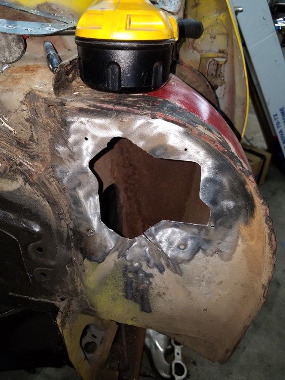
Once the wheel well openings were both raised 2.25 inches, it was time to patch the inner fender together. The photo above shows the clearance I have a 1" of suspension compression.... which is to say, not much. My goal is to have zero rubbing for any wheel position at 1.5" of suspension compression, and have 75% of my steering range at full bump.


In order to make that happen, I had to cut off the two tabs that held the clip nuts that are at the 10 and 1 positions on the wheel. To replace that, I drilled and tapped some flat stock, and spot welded it to the fender. I then cut the portion of the inner fender off that bolted to the fender opening, and attached it. Then, it was a matter of filling in the gap.


With the inner fenders done, I removed the front fenders and found this rust happening under the window trim. I'm not sure how best to repair this... but I'm going to deal with it later.


Maybe I should just omit the fenders... looks pretty cool!

On to the windsheld wiper motor relocation!
Given how far the motor is recessed into the firewall, the stock wiper motor mount was obliterated. So I read through SevenZeroNova's guide on a relocated wiper motor and purchased a wiper motor and transmission out of a 2001 Pontiac Bonneville.

Motor With Mount plate:


Plate that will weld to the firewall:


And the hole in the firewall:


Now, with the motor mounted I ran into a couple of issues. First among these is that there was not a way to run the linkage directly from the motor arm to the middle wiper pivot.

the other issue was that the linkage is worn out.

To solve the first issue, I built a pivot arm that bolts to the firewall about where the trim tag goes. The second of the pics below shows about where it installs, but it goes inside the cowl and will barely be visible.


To solve the other issue, I borrowed some more of the Bonneville wiper system. It turns out that if you grind of the riveted in ball studs, the shank is about the same size and offset from the wiper pivot plate. I simply moved the boneville's larger ball stud to the Nova's middle wiper stud's plate... and tacked it in! This works for the linkage that goes from the middle wiper stud to the driver side stud, but you have to cut off the ends of the linkage and weld the Bonneville's in place.


I am waiting on the special bolts that hold the wiper pivots in place. I broke most of mine!
Reply With Quote
  #14  
Old 05-14-2018, 04:14 PM
nickcornilsen's Avatar
nickcornilsen nickcornilsen is offline
Member
 
Join Date: Oct 2011
Location: Roseburg, OR
Posts: 86
Thanks: 0
Thanked 32 Times in 17 Posts
Default

April 2018

Onward to the dash panel area... turns out I had a little bit of the windsheild corner cancer. There is alot of info on how to fix this. And I didn't take pics of the repair.


With that done, I took some parts to be sandblasted, and stripped the firewall and front chassis of rust/mill scale and got it ready to primer.

Here it is done!


A bit of a tangent... but I had the Drive Shaft Shop narrow up my CV Axles and make a carbon fiber driveshaft for use in the Corvette torque tube! They were 8 weeks in the making, but well worth the wait! After verifying the length, they're going into storage for now.

Reply With Quote
  #15  
Old 05-15-2018, 09:25 AM
WILWAXU WILWAXU is offline
Lateral-g Supporting Member
 
Join Date: Mar 2008
Location: San Diego, CA
Posts: 1,012
Thanks: 1,207
Thanked 131 Times in 86 Posts
Thumbs up

That's a TON of work! Great project, keep pushing forward.

Thanks for sharing
__________________
John Brown
Instagram @wilwaxu
Facebook @wilwaxu

Last edited by WILWAXU; 05-15-2018 at 12:45 PM.
Reply With Quote
  #16  
Old 05-15-2018, 12:23 PM
WSSix WSSix is offline
Lateral-g Supporting Member
 
Join Date: Nov 2008
Location: Dunwoody, GA
Posts: 6,473
Thanks: 1,016
Thanked 706 Times in 551 Posts
Default

Coming along well, Nick.
__________________
Trey

Current rides: 2000 BMW 540i/6 and 86 C10.

Former ride: 1979 Trans Am WS6: LT1/T56, Kore 3 C5/6 brakes, BMW 18in rims
Reply With Quote
  #17  
Old 06-26-2018, 10:05 AM
nickcornilsen's Avatar
nickcornilsen nickcornilsen is offline
Member
 
Join Date: Oct 2011
Location: Roseburg, OR
Posts: 86
Thanks: 0
Thanked 32 Times in 17 Posts
Default

Update time!

Since my last update, I have been focusing on the rear half of the car again.


The above photo shows me starting on the access hatch for the rear transmission. This is how I'll get to the shifter linkage to detach it for engine removal.


Sometimes you just have to get a glimpse of the end product, right?


What I leanred by moving the car up like this is that
A) A 315/30 rear tire looks disporportionate to a 265-40 front. So I have a 295/40 on the way.
B) Somehow the rear 'axle' centerline got moved forward in the chassis by 1/2". I can align my way out of that, though.
C) I don't have to raise my rear wheel well openings. I think it looks fine like this. I will raise the back by another inch though, to help even it out.


I got my order of sheetmetal! All AMD products.

Last edited by nickcornilsen; 06-26-2018 at 10:09 AM.
Reply With Quote
  #18  
Old 06-26-2018, 10:06 AM
nickcornilsen's Avatar
nickcornilsen nickcornilsen is offline
Member
 
Join Date: Oct 2011
Location: Roseburg, OR
Posts: 86
Thanks: 0
Thanked 32 Times in 17 Posts
Default


This is the trunk. To keep fumes down, I decided the fuel cell needed to be completely under the floor. The cell was mounted as low as possible, and I bought a thread-in cover with an O-Ring that goes in the trunk floor.

I didn't have the budget for an outside filler neck, so I thought this was a reasonable compromise.

At this point, I'm going to finish the floor boards and seat mounts, then do another round of primer! Then, I'll be going after the rear body sheetmetal.
Reply With Quote
  #19  
Old 06-26-2018, 01:29 PM
rustomatic rustomatic is offline
Senior Member
 
Join Date: Apr 2014
Location: ATL
Posts: 748
Thanks: 11
Thanked 58 Times in 36 Posts
Default

Great stuff, man! This is the kind of build I like to see. More of this is needed!
Reply With Quote
  #20  
Old 06-26-2018, 02:31 PM
Ketzer's Avatar
Ketzer Ketzer is offline
Lateral-g Supporting Member
 
Join Date: Feb 2008
Location: Eads, TN.
Posts: 1,446
Thanks: 330
Thanked 151 Times in 104 Posts
Default

Very cool project!

What are you shooting for on ride height? (rocker to ground in inches)


Jeff-
__________________
You remind me of the timing on a turbo engine...
Reply With Quote
Reply


Posting Rules
You may not post new threads
You may not post replies
You may not post attachments
You may not edit your posts

BB code is On
Smilies are On
[IMG] code is On
HTML code is Off

Forum Jump


All times are GMT -5. The time now is 12:19 PM.


Powered by vBulletin® Version 3.8.11
Copyright ©2000 - 2024, vBulletin Solutions Inc.
Copyright Lateral-g.net