So a few people have ask, so I guess I'll dig through some pics and see if I can get this thread a little more up to date.
Last update was the headers. They are finish welded, and happy to say removable with the engine in place. They do allow access to plugs and flange bolts. To complete those, I added EGT and O2 bungs to each primary:

If you're wondering why have both EGT and O2? The O2's will be used during initial tuning to trim cylinder-to-cylinder fuel balance. They won't live very long pre turbo due to the heat. Once the cylinder trim is complete and all individual cylinders are at lambda, the O2's are removed and capped. The EGT temp will then become the baseline threshold for each cylinder at lambda.
All O2 sensors are pressure compensated, meaning they are designed to provide accurate data at roughly atmospheric, give or take a few psi. As back pressure in the header increases (with a turbo), the pressure will skew the O2 data and that has to be compensated for. There are a couple of ways to do this, start with an ECM capable of pressure data conversion, a stand alone O2 controller that does the conversion internally and busses the massage to your ECM, or the ability to write your own maths table in the ECU and have the O2 data. Having the pressure offset data for each make and model O2 is critical, so you have to see which O2 each method supports.
The ECM I am using does this internally, so all I have to do is provide back pressure data.
I just need to feed 800 degree gas to a pressure sensor!
I used a stainless NPT bung and attached a 3' stainless tube to allow the gas to cool off enough that the sensor wouldn't melt.

Because this pressure tap is in the collector, pre turbo, it sees the individual cylinder pulses, and without some way to smooth these out, the pressure data will look very spiky. At the end of each tube is a pressure spike diffusing can with the pressure sensor on the other end. Basically where the pressure can equalize before being read as data and sent. And as a bonus, a little more heat dissipation. These little guys have stainless mesh inside.

Alright, enough of all that!
With the headers built, I wanted a way to support the turbos, keeping the weight of them off the headers. I hung the turbos off a wire to find the balance point. It just happened to be where the exhaust turbine attaches to the center section. I removed two retainers and made a pattern for a stainless bracket:

I then attached a support bar from the chassis with a high temp rod end for the turbo to "hang" from:

With the turbo's in position, headers where they were, time to connect them all together. The collectors I'm using are double slips, so i decided to use double slips anywhere I needed to exhaust to be able to expand without cracking.
This pipe connects the header to the turbo, with the waste gate outlet. I added gussets to the waste gate flange and V-band flanges on the end to prevent cracking as long as possible:

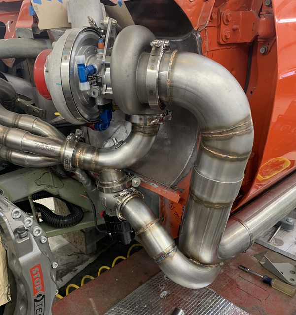
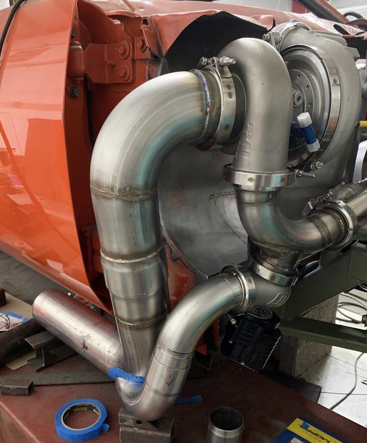
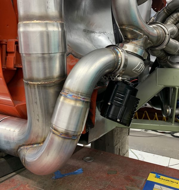
On to the down pipes and waste gates. I'm running electric waste gates controlled by my ECM. I HATE the sound of straight pipe waste gates, so wanted to incorporate them back into the down pipes so they went through the muffler.
You can see a double slip on the waste gate discharge and down pipe:


Tough getting in tight spaces!


Washers for O2 bungs:


