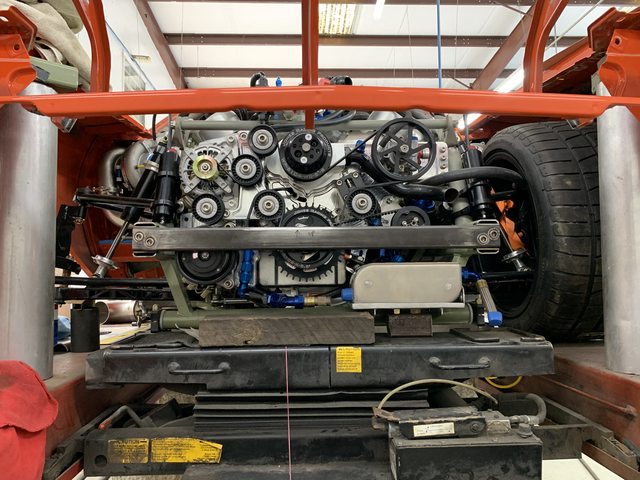
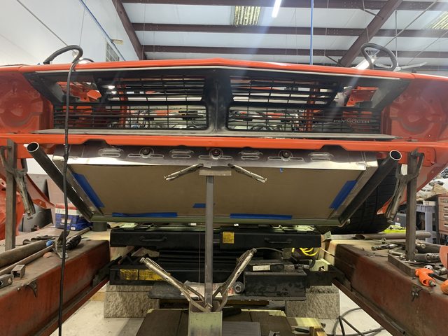
For the engine, I wanted to use a motor plate to mount it. This was going to be tricky because I'm running a 5 stage dry sump
with A/C. I'm also running a Viper 180 amp alternator (PWM regulated from my ECM), KRC power steering pump, and a Mezierre billet mechanical pump (universal).
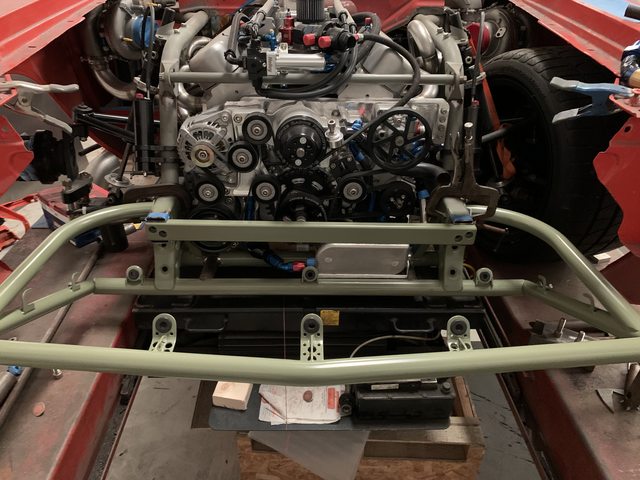
I'm running a Jesel belt drive, and really don't like that 3/4 of the belt is exposed, just hanging out there waiting for something to get in-between the belt and drive, at least that's my fear. I wanted to enclose the timing belt, and had the idea of having a motor plate thick enough to accomplish this. My idea was to have a cover plate that would also mount the water pump. I picked the billet universal Meziere pump because the back is removal, has exceptional GPM flow at idle and full speed, and great pressure. What if the back of the pump could also be the time belt cover? This was my line of thinking. Then this plate could also hold the cam sensor.
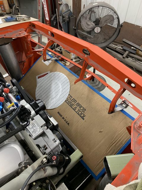
Time to figure out if any of this would even work. I started laying out accessories in different configurations until I found one that looked promising. I had to make sure that everything that connects to the different accessories would also clear everything else. I built a quick wood buck I could mount to the engine and hang the accessories from. When it looked good, I measured it out and made a .DXF CAD file, that I then printed. I recut a wood buck to the new printed version and laid it out again. So far, so good.
Now I needed help. I called Aaron Oberle and ask him if he was interested in the project. He was. This was either right before or right after he got his Haas Mini Mill, can't remember.
I sent him the .DXF I made, and I want to thank Jesel and Meziere for providing .DXF files of the Jesel timing cover and Meziere water pump back. This saved a TON of time.
Aaron did his SolidWorks magic, making my Fusion360 magic look like a toddler, and got started. In the meantime, I bought a cheap granite surface block and height mic to start the process of measuring all the accessories. All mounting locations reference off pulley height, overall dimensions, etc.
Once everything was modeled, it was time to see if it would actually fit. I had the motor plate CNC routered from MDF and Aaron 3D printed the accessory brackets:
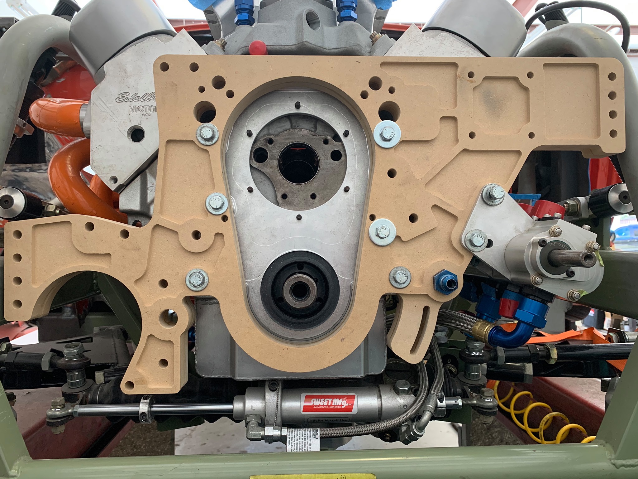

I was able to mount all the accessories to the plate and check fitment. Couple of small tweaks and I was good to go, or so I thought. Aaron's machine wasn't big enough to do the motor plate, so I shopped it around to about everyone with no takers. I mean flat out, "Nope, not something we're interested in doing". Okay wow. So Aaron said he would do everything and sub out the big motor plate. And here is what he made:


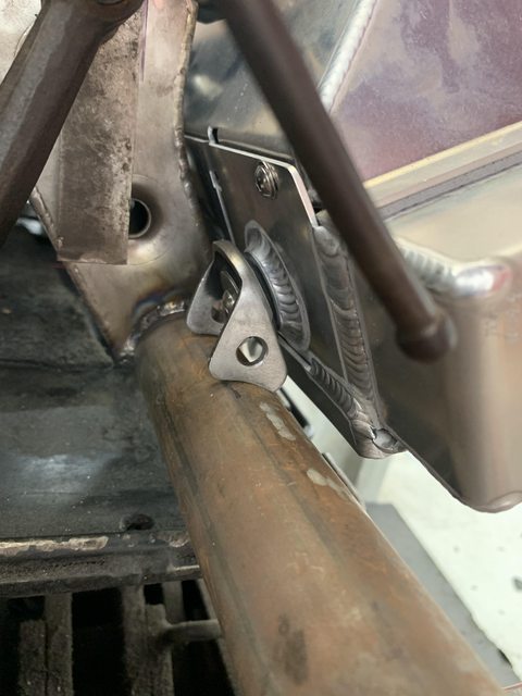
So how this goes together. The Jesel timing plate bolts to the engine. You'll see the funny looking bolts in the top. I had Aaron make those so the plate dowels onto to cover. This not only keeps the plate in alignment, but also lets the timing cover stay bolted and sealed to the engine when the motor plate is removed. The biggest reason is that the cam sensor is attached to this setup, I wanted to be able to service the plate and keep the position the same.
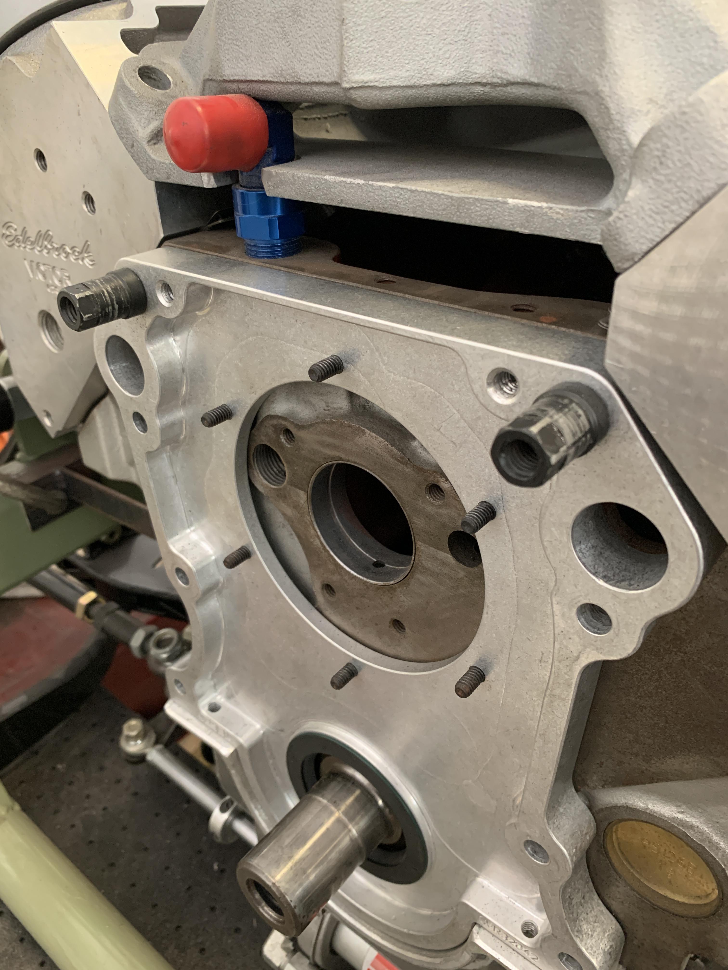
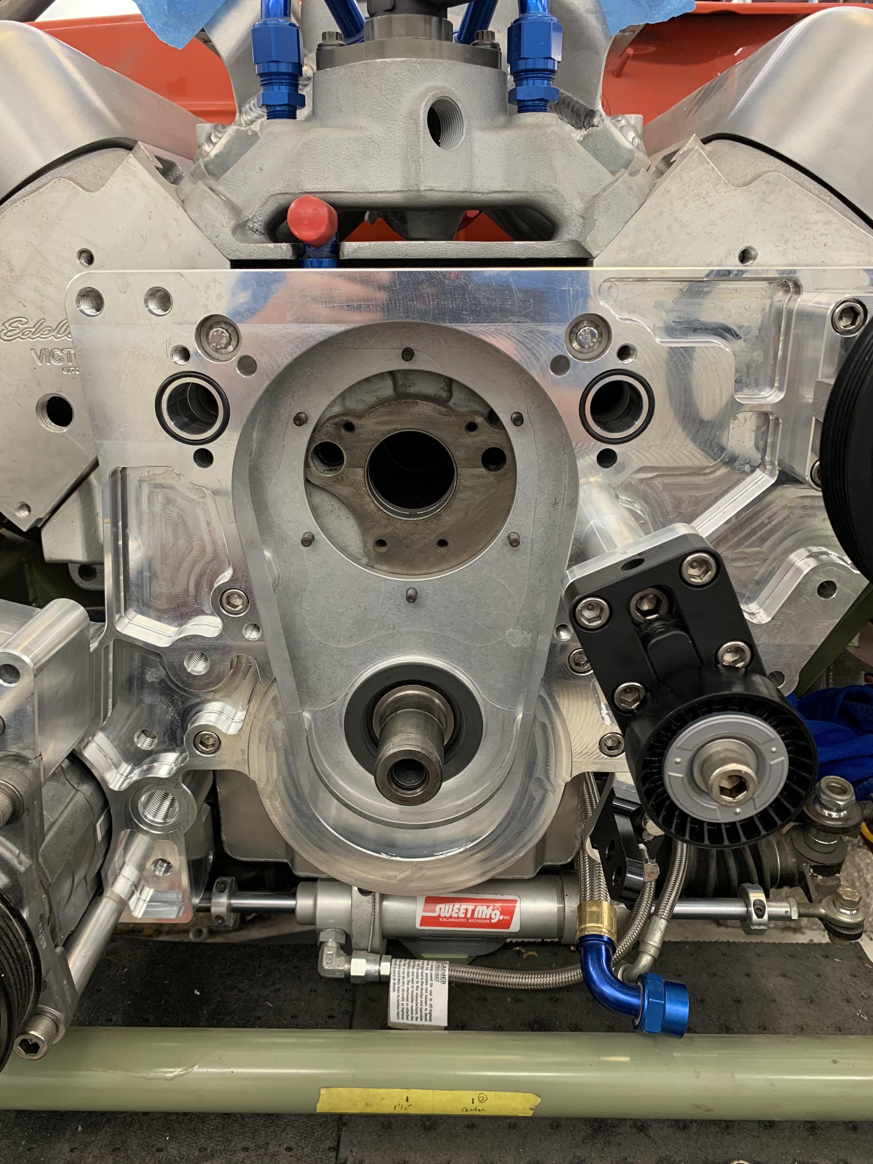
Then the motor plate bolts through the Jesel timing cover (which is doweled to the block). Had Aaron use O-rings to seal all the parts together. Note the machined in bracket for the crank trigger:

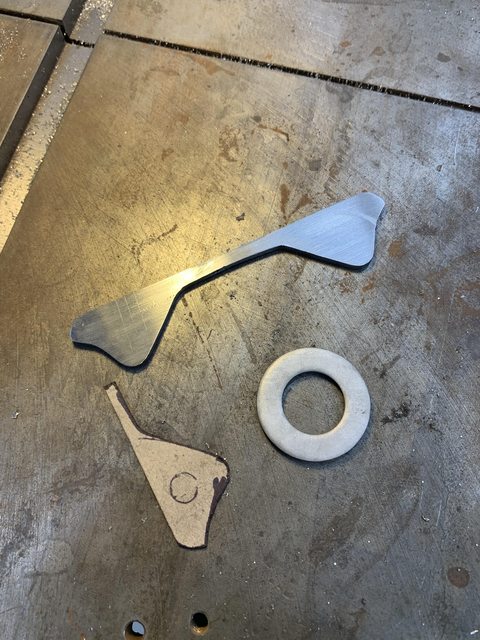
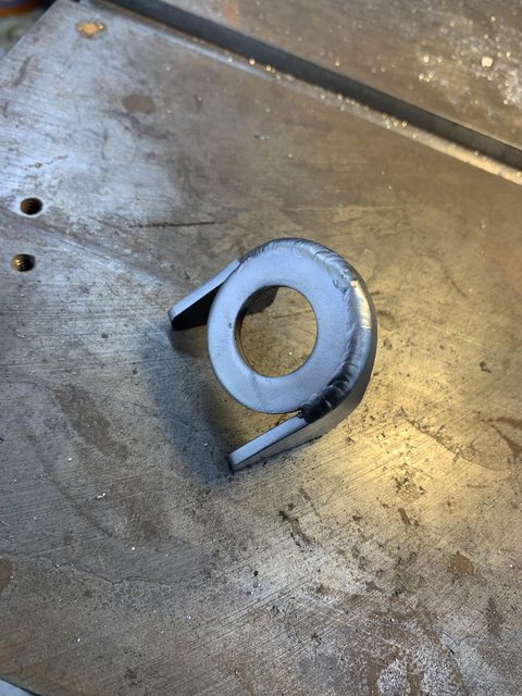
This shows the tensioner that Aaron made. I couldn't find one that would work in the space available, so had to be made.
And now the timing cover (also doweled to the plate) that started this whole thing. You can see how it incorporates the cam sensor. This is the backside that bolts to the motor plate:

And the Meziere pump bolted to it's new back/timing cover. Billet timing pointer at the correct depth to actually be on top of the balancer marks!

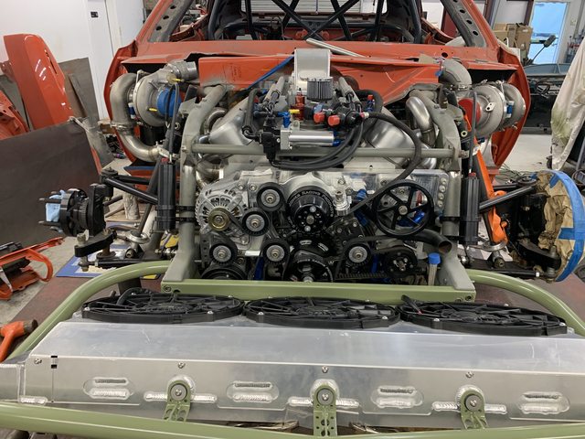
From an idea, to a CAD model to finished product. Lots of back and forth trying to get the maximum belt wrap on the accessories. This required 3 idler pulleys and the tensioner pulley. All idler pulleys are Gen 3 Hemi. Never see an issue with them and readily available.
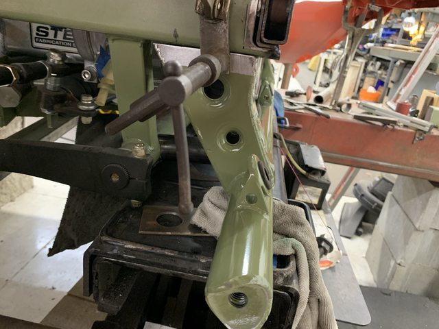
I mounted all the accessories to the plate and then used the height mic off the motor plate surface to check the pulley heights. They were all within .005". So calling that a win!

Couple of things to note in the pic above. I run water from the pump into the front of the block, as well as between the middle cylinders on the side of the block. The line that runs down from the water pump backing plate feeds those. The plate has ORB fittings so I can pass through.

The little belt routing pic will be laser etched on the bracket.
Speaking of belt, this brings up the pulley situation. Believe it or not, the A/C compressor kinda dictated pulley sizes for everything. I can't change it's diameter, so I had to size the crank pulley to drive it at the correct speed. Once I had the crank pulley size, then I could size everyone else with removable pulleys. Meziere gave me the cavitation speed of the water pump, so had to have Jones custom make that one because they only offered that depth/size in a V-belt. Jones also made my crank arbor and crank pulley. The KRC pulley size keeps the P/S pump out of cavitation, and finally the alternator pulley was changed to match the same ratio as the Viper. Lots of amps at idle!


 Brian Hobaugh SCCA National Tour June 2014
 First Hemi 'Cuda Convertible Ever Built
 Short clips: Goodguys Pleasanton autocross and pit videos


 It's like a ball of yarn unwinding, that has no end... Author DKz Garage
 Linear Mode

