|
|

01-02-2016, 02:39 PM
|
|
Senior Member
|
|
Join Date: Mar 2014
Location: Plano, TX
Posts: 160
Thanks: 6
Thanked 67 Times in 33 Posts
|
|

Project Update January 2nd, 2016: This forum post update covers work we did to the 69 Camaro in October of 2015. This included front splitter layout, front splitter structural mounts, some suspension and shock questions, front brake ducting, air intake tub and airbox, upper grill, some initial radiator ducting, and more. Some of the "work" was just conversing with the customer to finalize the look for certain things, or reasons why we wanted to not use an existing part, which I won't bore you with here. Just the pics of the work completed and the reasons behind the parts or design choices.
Just a quick shout-out to Lateral-G forums. This build thread was added there after a moderator reached out to me last week and said "bring it". If there's another forum where you think this build thread would be welcomed (and you are an admin or moderator there) please send me a PM and we'll take a look.
LOWER SPLITTER DESIGN & FABRICATION
There have been some hours spent on the front splitter design over the past 3 months, perfecting the dual plane splitter design that we have come to now. The work below was from early October and the design based off a lot of back-and-forth discussion with the car owner and us, where we refined our engineering / aero / fabrication goals and merged them with the aesthetic look he had in mind.
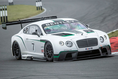 
We took inspiration for the final splitter from a certain racing series where some recent rules changes have allowed for better splitter designs - and where multi-plane splitters on sedans and coupes has arisen (one example is above left). We do caution folks when looking at pro racing series for aero design inspiration, though, because this is one area that is almost always heavily regulated by strict rules. Race engineers have to come up with lots of tricks to exploit rules loopholes, which might not apply to your build. (exception: World Time Attack has almost unlimited aero rules) This 69 Camaro isn't really being built for any racing class (after long discussions with the customer) so we can "go nuts" with aero. This car is still being built around a budget, and looks do matter, so the customers "intended use" makes some of the "unlimited" front aero tricks unfeasible (see above right).
There was a bit of compromise on both sides for the splitter and front valance. In the end (it is nearly done now in January) I think the splitter and front end looks amazing, is very strong, should make ample downforce, push air past three heat exchangers, feed two brake cooling ducts, and keep the intake airbox filled with high pressure ambient air. All sorts of systems are tied into the splitter so this was a pretty big chunk of this project.
Jason has a specialty in fluids engineering so he worked directly with our fabricator Ryan to lay out the airflow paths and put the splitter where it needed to go. They also discussed splitter length, as we tend to run more extension than others. Why? Because we've tested it, and a longer chord works better in most cases.

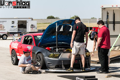
Vorshlag has built and tested a number of splitter designs for a number of different cars. We used 3 different splitter designs and lengths on the 2011 Mustang above, which I raced in NASA competition events for 5 years. We were told by some that the 10.25" extension on the splitter shown above "wouldn't work", but in fact it worked too well and overpowered the rear wing we ran at the time.
The long splitter length and low height made loading the car onto our trailer a total bear (even with 12 feet of ramps), and scraping the pavement driving around in even a somewhat smooth paddock was common. We later made another splitter with only a 6" extension past the nose, and that was much more user friendly (even somewhat streetable), and still made ample front downforce - when coupled with a lower grill inlet duct, a ducted hood, and blocked off upper grill. I will come back to that set of "grouped mods" below.

Ryan took Jason's engineering direction, some "inspiration" pictures I provided, and his own experience and built a mock-up of the lower plane of the splitter in MDF. This was built with a certain amount of extension past the front bumper, and fixed at a certain height from the ground - not too close to make it impossible to load on a trailer or get taken out by a simple off track excursion, but not too high as to ruin the ground effect we're going for. We sent several images of the mock-up to the customer, then moved into metal when he approved.
 
Some have questioned our use of aluminum plate for front splitters in the past, but we have explained that in detailed replies before. Short version - there are 3 materials we feel are appropriate for front splitters: plywood, aluminum plate and carbon fiber. We don't like Alumilite or other corrugated "sign shop" materials for a number of reasons, mostly because you can permanently deform that between two fingers. This stuff tears easily and the force of air pressure alone has made more than a few Alumilite splitters fly off - one of which then caused a crash on the car if flew off of, as seen in a certain high profile race event a year ago.
 
Plywood has its place in racing (usually in lower budget endurance, W2W or Time Attack cars) and we've even used plywood on the Hillclimb Subaru, shown above. We chose plywood here because of high level of abrasion on the paved Pikes Peak mountain hillclimb course + the low cost for each unit allowed for multiple spares. Carbon is the lightest/strongest choice, but too pricey for anyone but pro race teams to use and beat on (and we are not a "composite shop"). That leaves aluminum - which is easy for us to fabricate, has a relatively low material cost, and has a good strength-to-weight ratio. We could talk for days about the pros and cons of splitter materials, but I'm going to leave it at that so we don't get too sidetracked.
continued below
Last edited by Fair; 01-03-2016 at 09:47 AM.
|
01-02-2016, 02:40 PM
|
|
Senior Member
|
|
Join Date: Mar 2014
Location: Plano, TX
Posts: 160
Thanks: 6
Thanked 67 Times in 33 Posts
|
|
continued from above

Ryan transferred the buck to 1/8" 6061-T6 aluminum plate and that was cut out with a saw by hand. No fancy CNC water jet in our shop (yet) so he did it "old school". Green tape, Sharpie lines, careful measuring, then a jig saw with a steady hand. The edges are ground and cleaned up to remove a sharp edge and it then get's mocked up on the car, above.

Did you notice what changed in the second metal splitter picture above? Look closely. There's a change in splitter height at the ends when compared to the middle. This "channel" was done for engineering reasons as well as for aesthetics. Its a long story, but basically this slightly taller center section feeds some additional air under the car to the rear diffuser (which we will be building very soon).
 
You can see some fabrication of the lower grill ducting to the radiator, and a little bit of this changed later. The splitter design and fab work spanned over 3 months to get it all just right, so that will be shown in upcoming posts to this thread.
FRONT LOWER VALENCE DESIGN & FABRICATION
This is an important part of the "look" of this car, so dozens of emails, sketches and calls with the customer went over how the front lower grill opening and aero bits would look. The front splitter and valance, along with the hood, will be the key visual aspects of this build. And are also very important for making front downforce.
 
We mocked-up a lot of different designs until we came up with one that worked for his tastes as well as fed the heat exchangers and brake ducting properly. We could have done this a lot quicker and more cheaply, but it wouldn't have looked as good nor pleased the car owner.

I had hoped to keep the factory foglight holes in the lower valance but lost that battle. The design we all eventually agreed upon would be a lot more work to make, but it also looked better and has more lower opening surface area than our earlier designs. Basically there are three vertical openings that won't make sense until I sneak in some pictures from December, where it is nearly complete. Getting there took a couple of iterations to make it look like the owner wanted.
 
These two pictures above are after one dead end start, and another revision to this layout, where it was finally getting closer to the look like he wanted. There are coolers mounted in these pictures that have to be fed and have to exhaust heat, with a lot of other considerations as well. We will get to those details in later updates.

Again, I don't want to spoil too much from future posts (November + December work will be in the next 2 posts) so I'm going to leave it there and show the remaining lower valance work in due time.
continued below

|
01-02-2016, 02:41 PM
|
|
Senior Member
|
|
Join Date: Mar 2014
Location: Plano, TX
Posts: 160
Thanks: 6
Thanked 67 Times in 33 Posts
|
|
continued from above
UPPER GRILL BLOCK OFF PLATE
The front grill openings on older cars, and even modern designs, are sometimes pretty massive - creating extra drag. The 1969 Camaro front end had all of the cooling air coming from a very large upper grill, as shown below. These large front openings were often deemed necessary to keep cars cool in the worst stop-and-go traffic, in the hottest climates, with air conditioning running on full blast.
 This is what we had to start with - more in common with a truck than a sports car
More modern sports cars have gone away from large, open grills to more limited front openings. The most modern, aero inspired designs push the grills closer to the ground, and we're starting to see a few OEMs that even duct the waste heat out via massive hood openings (see the C7 Corvette, below). This is a trick that can be packaged in new designs to create some extra downforce (or eliminate lift).
 This is more what we're shooting for...
One of the things I mentioned that we've tested (from previous track testing and splitter work) was blocking off the large, open upper grills from a typical "flat front end" car, like the 1st gen Camaro or the modern Mustangs and Camaro coupes.
 
Since this 69 Camaro is being built primarily for track use we're going to cut down some drag and force high pressure air where it can do more work - to a newly created lower grill opening. Blocking the upper grill puts more air through this smaller lower opening, right above the splitter, which in turn helps create downforce. This is amplified when the air has a better place to exhaust - through massive, ducted openings in the hood placed in the right places. That's another big part of this project we will will expand upon in later posts.
 
And there is a lot more than just "making a lower opening" - there has to be inlet ducting sealed to the front sheet metal and to the heat exchangers, to force air through instead of around the radiators. The images above show that on our shop Mustang - with the front end removed you can see the duct boxes and routing of air from the lower grill.
 
For this car Ryan first took the new OEM style, reproduction, plastic 1969 Camaro grill and made templates in cardboard to block the back side openings completely. The goal is to keep the "look" of a stock 69 Camaro SS grill, but with aluminum sheet mounted behind it keeps the airflow through the upper opening to "zero", forcing more air over the hood or towards the lower grill opening - and reducing drag. It won't be as effective as the smooth grill plate we did on the Mustang shown above, as the protruding plastic mesh grill in front of the block off plate will add a little drag, but its the best compromise between looks and performance.
 
The templates were turned into four portions of aluminum structure, with the two middle sections welded together. The outer sections bolt onto the back of the grill, outboard of the headlights (which have a bit of airflow normally). The two conjoined inner portion bolts on to block out the majority of the middle grill surface, with a near air tight seal to the plastic grill structure.
continued below
|
01-02-2016, 02:42 PM
|
|
Senior Member
|
|
Join Date: Mar 2014
Location: Plano, TX
Posts: 160
Thanks: 6
Thanked 67 Times in 33 Posts
|
|
continued from above
 
This "grill block-off" plate was later modified to feed the air filter box. This was deemed necessary after the various heat exchangers were placed and duct work to the hood was laid out. Now a small portion of the original radiator airflow from the upper grill will force feed the engine for a small "ram air" effect. Those bits are shown below.
And yes, the raw aluminum grill plate will be painted or coated black later in the build, to help "hide" the bits behind the grill. This will give a more subtle and OEM look to the upper grill, at least.
RADIATOR DUCTING FAB (PHASE 1)
There was some initial work done in October to make the intricate lower grill opening duct work. These bits are in front of the radiator and create sealed pathways for airflow to move from the various splitter openings to the 3 heat exchangers and two brake ducts.

This lower radiator ducting fabrication was started in October but only just wrapped up in December. It took many hours. Other than this teaser shot above, I will save the rest of the pictures of this phase of fabrication for a later post.
AIR INTAKE BOX & INLET TUBE FAB
Like I said above, things underneath the hood started to get cramped once the hood ducting was being laid out. The initial hood ducting layout steps began in October, shown below with cardboard and aluminum sheet showing potential routing of exhaust heat. During this step we figured out a number of constraints, so Ryan went ahead and built the intake tube and airbox.

The solution was to bypass all of the possible routes for hood exhaust ducts and push the air filter box to the front in a nice, high pressure zone: the back of the blocked off upper grill. The massive engine setback of this LS3 plus the rolled radiator placement made for a really L-O-N-G intake tube, as you can see.
 
Brad and I snapped a few pictures of these components as they were being built. The airbox bolts to the grill plate (with weather stripping at the edges for an air tight seal) and the air tube bolts to the airbox, then has a hose coupling at the throttle body. The back plate unbolts from the rest of the air filter box structure, for access to the air filter inside.
 
That doesn't look like much but there was some thought that went into the air inlet tube and air filter box parts. At right above, the finished parts are sitting atop the mock-up flat steel hood we used for some duct layout work. The mocked up cardboard ducting is shown upside down in that image.... deep ducts.
 
On some other ducted hood setups we have built before (see above) the hood duct was pretty straight forward - a sealed duct box was built from the back of the radiator to the hood. In that type of layout you re-route the intake air tube laterally and around the hood duct. This setup puts the inlet air filter in an airbox mounted off to the side of the heat exchangers.
continued below
|
01-02-2016, 02:43 PM
|
|
Senior Member
|
|
Join Date: Mar 2014
Location: Plano, TX
Posts: 160
Thanks: 6
Thanked 67 Times in 33 Posts
|
|
continued from above
 
On the 69 Camaro we had less latitude on the placement of the hood exhaust ducts. We spent many hours (only a faction of the options are shown above) trying to find a way to duct the 3 heat exchangers and fit inside the confines of the OEM style, aluminum, 69 Camaro cowl hood. The raised cowl section just did not lend itself to placing the large hood ducts we needed in the proper places (ow pressure zones - which helps extract air).
Then we tried an flat 69 Camaro hood and had new styling constraints for the ducts. Even the front tires themselves limit where the ducts can be on the hood - stuff 315s under stock fender contours and they begin to intrude inboard, in a big way (shown above right at "full bump travel"). I will expand on this when we finally have the new hood installed (a composite hood is being built now) and the final hood ducting design is under construction. These ducts are gonna be BIG.

The "straight on" approach for the inlet tube we used on this 69 Camaro is the cleanest routing for the intake air and should work fine here. This produces the cleanest, straightest path for air to get to the engine (only one small bend in the inlet tube, behind the airbox).
 
A big K&N filter is stuffed inside the airbox and it draws air from two open grills in the upper grill section. The filter element is visible inside those grill openings in the grill block-off plate pictures in that section above. An LS3 style Mass Air Flow sensor "blade" will be added to the intake tube ahead of the throttle body later in the build.
FRONT BRAKE DUCT FABRICATION
 
The car came in here with 2-piece 14" Wilwood front rotors and some 6-piston calipers installed up front. Well as big as those are, for longevity on a road course this car still needs some forced cooling air thrown inside the at least the front rotors. Ryan fabbed up a pair of custom brake backing plates with 4" inlets to keep these cool.

Simple aluminum plate was laid out and cut to fit around the C6 Corvette front spindles / hubs and seal to the inside face of the 14" rotor. The 4" oval tubes were made on the tubing roller and welded to the backing plates, then fitted with 2-layer, high temp, 4" ID brake duct hose routed to inlet ducts in the splitter (which I will show later).
continued below
|
01-02-2016, 02:44 PM
|
|
Senior Member
|
|
Join Date: Mar 2014
Location: Plano, TX
Posts: 160
Thanks: 6
Thanked 67 Times in 33 Posts
|
|
continued from above
 
No rocket science here, just careful measuring, some experience, and good craftsmanship. The main thing to remember is you want to get as much of the duct aimed below the rotor face. Blowing air directly at the rotor face doesn't do much cooling - but ducting air inside the rotor hat cools the front wheel hub and allows the vented brake rotor to act as a centrifugal air pump, which pulls the air through the rotor from the inside out. Even without ducted air the rotor will do this on its own to a small extent, but high pressure air forced inside the rotor makes for a HUGE bump in brake cooling efficiency.

Along with the brake duct hose some November work is shown in the image above. I will talk about what's coming up in the final paragraph of this update.
SPLITTER MOUNT FABRICATION
All of the factory front structure is gone, from the radiator support to the inner fender unibody structure. There are critical items that need a solid piece to be hung from at the very front - like the splitter, which can put 200-300 pounds of aero load through the small struts that mount at the leading edge of the the lower splitter plane. There are also other pieces that need some mounting structure at the front of the engine bay, like the radiator, coolers, headlights, front bumper, and more.
 
The exterior "bumper" is an aluminum OEM reproduction unit, mostly added for styling (it covers several seams between OEM panels). Underneath this black aluminum bumper is the real structure added, by way of a 1.0" diameter DOM tube. This piece of tubing is bent to follow the contours of the OEM front bumper and then many things were tied onto this structure.
 
Reproduction OEM headlight buckets were mounted at the bottom using custom brackets welded to this 1" front structural tube. There are also splitter support rod mounts that attach to this front tube, with brackets hidden behind the exterior of the black aluminum bumper.
 
More things were then added to this bumper, like structure to mount the various heat exchangers, which we will talk about next time.
WHAT'S NEXT?
That's it for the October work, but there was a lot accomplished in November which I will show next time. This includes finishing the steering shaft, power steering and oil cooler mounting, front anti-roll bar "splined arm" and end link fabrication, fitting the front body panels better to finalize some mounts, a big discussion of hood and duct choices (including flat hood vs using the existing aluminum cowl hood), making a new front steering arm that bolts to the C6 spindles, then making new tie rods to finish the steering, planning out the wiper motors, making room for the driveshaft at the rear of the frame, as well as some exploratory work on hood hinges.

We will cover all that and more in my next update. Thanks for reading.
Cheers,
__________________
Terry Fair @ Vorshlag Motorsports
|
01-02-2016, 04:04 PM
|
|
Senior Member
|
|
Join Date: Oct 2006
Location: Colorado
Posts: 245
Thanks: 1
Thanked 3 Times in 2 Posts
|
|
Thank you so much for taking the time to post such a detailed build on this site. Wow-you and your shop have skills and I really appreciate the "everything for a purpose" type design. I for one had never heard of your shop (not sure how I didn't know about you guys), but now I need to research all you're builds.
Again, thanks for the build and inspiration! Top Notch!
Wes
|
01-02-2016, 06:58 PM
|
 |
Lateral-g Supporting Member and Moderator
|
|
Join Date: Oct 2007
Location: On Lake Ontario in NY
Posts: 11,477
Thanks: 3,590
Thanked 4,104 Times in 2,428 Posts
|
|
Bar...
...raised. 
__________________
Skip
|
01-03-2016, 07:18 AM
|
 |
Moderator
|
|
Join Date: Dec 2010
Location: Pacific Northwet
Posts: 8,034
Thanks: 33
Thanked 102 Times in 41 Posts
|
|
Great reading Terry, thank for taking the time to share all the talent within the walls of Vorshlag. 
|
01-05-2016, 11:33 PM
|
 |
Senior Member
|
|
Join Date: Nov 2012
Location: Vancouver,B.C. Canada
Posts: 206
Thanks: 1
Thanked 40 Times in 25 Posts
|
|
Man I'm out of breath! Great engineering and then some...really impressive work !!!
|
 Posting Rules
|
You may not post new threads
You may not post replies
You may not post attachments
You may not edit your posts
HTML code is Off
|
|
|
All times are GMT -7. The time now is 10:47 PM.
|


 Brian Hobaugh SCCA National Tour June 2014
 First Hemi 'Cuda Convertible Ever Built
 Short clips: Goodguys Pleasanton autocross and pit videos


 Linear Mode
