...

Go Back   Lateral-g Forums > Lateral-G Open Discussions > Project Updates
User Name
Password


Reply
 
Thread Tools Display Modes
  #31  
Old 10-07-2017, 11:03 AM
waynieZ's Avatar
waynieZ waynieZ is offline
Lateral-g Supporting Member
 
Join Date: Oct 2006
Location: Ma
Posts: 8,491
Thanks: 939
Thanked 342 Times in 231 Posts
Default

Nice fab work, and great project.
__________________
_Wayne________

___________________________________
https://lateral-g.net/forums/show...ghlight=FNQUIK
Reply With Quote
  #32  
Old 10-07-2017, 07:03 PM
WSSix WSSix is offline
Lateral-g Supporting Member
 
Join Date: Nov 2008
Location: Dunwoody, GA
Posts: 6,616
Thanks: 1,743
Thanked 918 Times in 683 Posts
Default

Quote:
Originally Posted by rustomatic View Post
Ditto! That is mid-engine as it sits--note the front axle centerline in relation to the heads. This truck is getting very cool.
You're right! I didn't even think about it that way. I was thinking have the engine behind the cab.
__________________
Trey

Current ride: 2001 BMW 540iT soon to be manual swapped.

Former rides: 1979 Trans Am WS6: LT1/T56, Kore 3 C5/6 brakes, BMW 18in rims

00 BMW 540i/6: Suspension, wheels, and ACS bits.
Reply With Quote
  #33  
Old 10-26-2017, 09:45 AM
TCI Engineering's Avatar
TCI Engineering TCI Engineering is offline
Member
 
Join Date: Feb 2017
Posts: 73
Thanks: 1
Thanked 12 Times in 8 Posts
Default

Haven't made much progress lately. Ed and I have been discussing the chassis center section and engine placement at length. There is no physical way to lower the engine in place so we've decided to build a removable lower section of the chassis. It will have 6 attachment points and allow the body/chassis to be lowered over the top of it. I've built this over and over in my head so many times that I get disappointed when I walk into R&D and see that it isn't physically built yet. I should start on it today though.

Much like the engine placement, cab placement is still up in the air. I had read and spoke to a few C10 builders that if you body drop .75" the bottom of the pinch weld will be dead even with the bottom of the frame. That's not the case on this truck. I am currently using our Camaro 3/8" spacers(which are roughly.75" less than the stock rubber mounts) between the cab and frame mounts and the pinch weld is still well below the bottom of the frame. On top of that the rear of the cab is lower than the front, using the frame as reference. This kind of works to my advantage though. I had kinda wanted to tilt/rake the whole body down a degree or two in the front. My plan is to make the bottom of the cab parallel to the bottom of the frame.

All of that means that the core support bushings will also need to be modified to assume the new angle. This pic is with roughly 1" less thickness.


I was at a stand still with cab placement because I wanted the pinch weld rolled up flat. I'm an OCD photog so i've seen way to many good looking trucks be ruined by the pinch weld.


-J
__________________
www.totalcostinvolved.com "Quality doesn't cost, it pays"

Last edited by TCI Engineering; 10-26-2017 at 11:07 AM.
Reply With Quote
  #34  
Old 11-07-2017, 10:51 AM
TCI Engineering's Avatar
TCI Engineering TCI Engineering is offline
Member
 
Join Date: Feb 2017
Posts: 73
Thanks: 1
Thanked 12 Times in 8 Posts
Default

Ed was working on shock placement while Sal and I were at SEMA. Here is what he came up with. This is basically our original upper shock mount raised another 7/16". She's going to be loooooooooooooooooooowwwwww.

__________________
www.totalcostinvolved.com "Quality doesn't cost, it pays"
Reply With Quote
  #35  
Old 11-20-2017, 09:26 AM
TCI Engineering's Avatar
TCI Engineering TCI Engineering is offline
Member
 
Join Date: Feb 2017
Posts: 73
Thanks: 1
Thanked 12 Times in 8 Posts
Default

SEMA, Pleasanton & Scottsdale, 3 weekends in a row working out of town has slowed progress on the C10.

We needed a little room under the cab for intercooler piping.


Still need to roll the edge to add some strength.


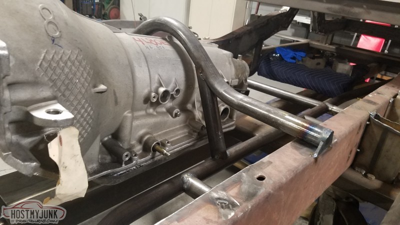
Started working on the chromoly center section. Form fitted around the tranny on the bottom side. The two middle tubes aren't mounted yet. There will be a couple cross braces added for the tranny mount & driveshaft loop.

*NOTE* The relationship between the front of the bell housing and the cab mount.


The Torque Arm will end up filling out this space so I needed to devise a way to gain clearance. It took some thought to get the angles right but the bend came out perfect (Even though chromoly deflects so much after being bent).

__________________
www.totalcostinvolved.com "Quality doesn't cost, it pays"

Last edited by TCI Engineering; 11-20-2017 at 09:32 AM.
Reply With Quote
  #36  
Old 12-05-2017, 03:07 PM
TCI Engineering's Avatar
TCI Engineering TCI Engineering is offline
Member
 
Join Date: Feb 2017
Posts: 73
Thanks: 1
Thanked 12 Times in 8 Posts
Default

Still plugging away on the center section. Built the main tranny hoop and tied it in with some downbars. It is just tacked in place at this time. I still need to throw the cab back on to confirm placement. It'll make sense why the tubes are on top of the frame once the cab is back on.


I still need to make a couple tabs to close out the round tube on top of the frame.


The rear tube placement must be 21" behind the front one to fit properly. I plan to tie the driveshaft loop, tranny mount and Torque Arm mount all together in that area.

__________________
www.totalcostinvolved.com "Quality doesn't cost, it pays"
Reply With Quote
  #37  
Old 12-07-2017, 03:21 PM
TCI Engineering's Avatar
TCI Engineering TCI Engineering is offline
Member
 
Join Date: Feb 2017
Posts: 73
Thanks: 1
Thanked 12 Times in 8 Posts
Default

We had our friends at California Rebuilt Exchange build us a quick ratio manual rack. Yes, that's right, a manual rack with what will likely be 315 or 335 tires on the steering axle. I better start eating all the spinach.

In all seriousness though. We are going to begin testing the feasability of running EPAS with our suspension. I figure that if it can handle this type of load & abuse then pretty much every other application will be just fine.


__________________
www.totalcostinvolved.com "Quality doesn't cost, it pays"
Reply With Quote
  #38  
Old 12-07-2017, 09:43 PM
Jr's Avatar
Jr Jr is offline
Senior Member
 
Join Date: Sep 2005
Location: so cal
Posts: 1,780
Thanks: 0
Thanked 5 Times in 4 Posts
Default

Which epas system are you going to test? There are a few popular ones in the market place...
Reply With Quote
  #39  
Old 12-08-2017, 07:38 AM
Jimbo1367 Jimbo1367 is offline
Senior Member
 
Join Date: Sep 2015
Location: USA
Posts: 312
Thanks: 81
Thanked 96 Times in 77 Posts
Default

Are you going to gusset the UCA mounts? Please say "Yes"
Reply With Quote
  #40  
Old 12-08-2017, 09:48 AM
TCI Engineering's Avatar
TCI Engineering TCI Engineering is offline
Member
 
Join Date: Feb 2017
Posts: 73
Thanks: 1
Thanked 12 Times in 8 Posts
Default

Quote:
Originally Posted by Jr View Post
Which epas system are you going to test? There are a few popular ones in the market place...
Ummmmm........junkyard...... lol

We will likely try both the Vue/Equinox and the Prius boxes. The Vue/Equinox appears to be more robust but has some "On Center" concerns. The Prius might be the easiest to adapt but just not sure of longevity under this much load.

Quote:
Originally Posted by Jimbo1367 View Post
Are you going to gusset the UCA mounts? Please say "Yes"
Yes, I will add gussets. That whole area will be tied into firewall down bars as well.
__________________
www.totalcostinvolved.com "Quality doesn't cost, it pays"

Last edited by TCI Engineering; 12-08-2017 at 03:24 PM.
Reply With Quote
Reply


Posting Rules
You may not post new threads
You may not post replies
You may not post attachments
You may not edit your posts

BB code is On
Smilies are On
[IMG] code is On
HTML code is Off

Forum Jump


All times are GMT -7. The time now is 04:30 PM.


Powered by vBulletin® Version 3.8.11
Copyright ©2000 - 2026, vBulletin Solutions Inc.
Copyright Lateral-g.net