Here's a little write-up which should give you the gist of the suspension situation.
Since neither of us have done anything like this before we decided to set modest goals for the design. This suspension isn't about pushing the envelope, pulling x number of lateral Gs, or extracting some set amount of tractive force from the tires. We're simply going for a stable and predictable car that avoids plowing in to crowded playgrounds at speed. Every design decision has reflected that sentiment and when in doubt, we've always erred on the side of caution. Any performance gains beyond that are considered a bonus.
Initial front-view swing-arm items like instant center, roll center, scrub radius, steering axis inclination, and control arm plane were established by laying out the steering rack, wheel, tire, brake rotor, and brake caliper in a SolidWorks sketch.
I then translated all the hardpoint coordinates over to a suspension modeling package called Lotus Shark. Shark allows you to jog the pivot points arbitrarily and see the resulting geometry change in real time. This kind of simulation is possible in SolidWorks but it requires all the suspension components to be placed in a finished assembly first. Obviously that can't be done since nothing has actually been designed yet.
The wheel offset was the major limiting factor in reducing scrub radius and steering axis inclination, which are still the two values I'm most dissatisfied with. The brake caliper was placed as far inside the wheel as was deemed comfortable, which determined the brake rotor position, which subsequently determined the lower control arm's outer pivot point. The final compromise ended up landing the scrub radius around 70mm with a steering axis inclination of 7 degrees. This is about twice what I would have preferred, but you can't (always) have your cake and eat it. :-P
Rear track is about 90mm narrower than the front (1430mm vs. 1320mm). This should reduce diagonal load transfer on corner entry and increase stability on corner exit.
The caster angle is 5 degrees both front and rear. This was done to simplify fabrication, as the same base upright can be used on either side of the car.
The front and rear static roll centers are 30mm and 65mm above ground, respectively. The front lateral roll center movement is less than stellar, but the control arms simply aren't long enough to affect any decent change in the area without completely ****ing up the camber curves.
Front camber in bump-roll is fairly linear with about -0.7 degrees per degree of body roll. In the rear it's slightly less aggressive at about -0.55. The camber gain could be considered small, but since the tires are fairly wide (285/30R18 front and 335/30R18 rear), it should be more than adequate.
The steering rack was placed in front of the front axle and below the axle centerline (as stock). This has the effect of creating an understeer tendency during lateral loading.
The front end has between 12% anti-dive, as well as about 20% Ackermann. In the rear there's about 25% anti-squat throughout the range of travel.
Our friend David "Mad-Dog" Madås was a huge help in getting the kinks ironed out, so I'd like to give a shout-out to him.
This is obviously a pretty superficial run down on the design of the suspension. If anyone has any other questions I'd be happy to answer them, but in the interest of full disclosure, be aware that I am by no means an expert. Literally hundreds of books by smarter men than I have been written on the subject.
In other news, here are some pics of the latest progress.
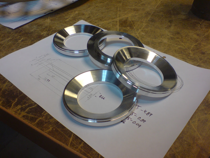
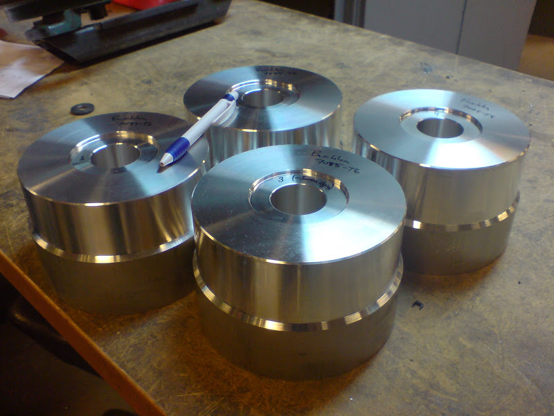
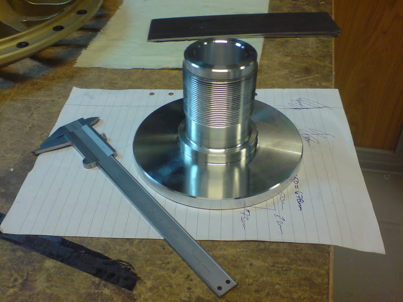
Alex finished the centering rings for the centerlug adapters in 7075-T6. The angled face contacts the nut and should also keep the wheels from deforming when we torque the nuts. They're out for black anodizing now.
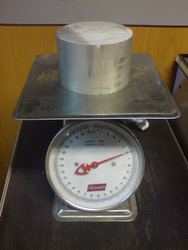
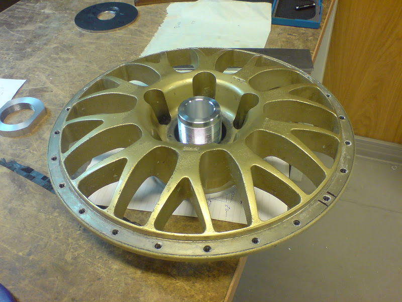
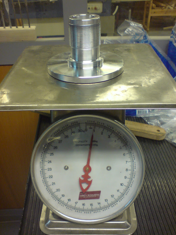
Alex also started on the centerlug adapters themselves. We had originally designed them as stainless weldments, but weight was an issue, so we decided to make them out of billet 7075-T6. These should end up weighing around 650 grams each, as opposed to 1.8kg. Hopefully we don't **** these up. The material was not cheap.
Start weight:
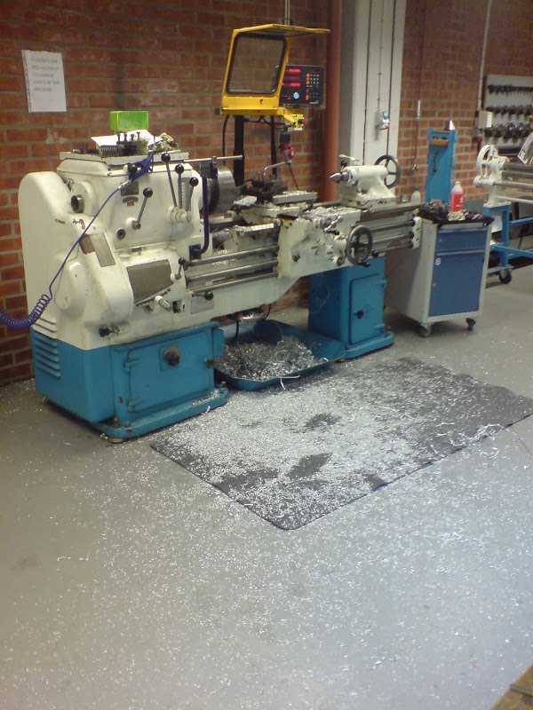
Getting the big boy drill out:

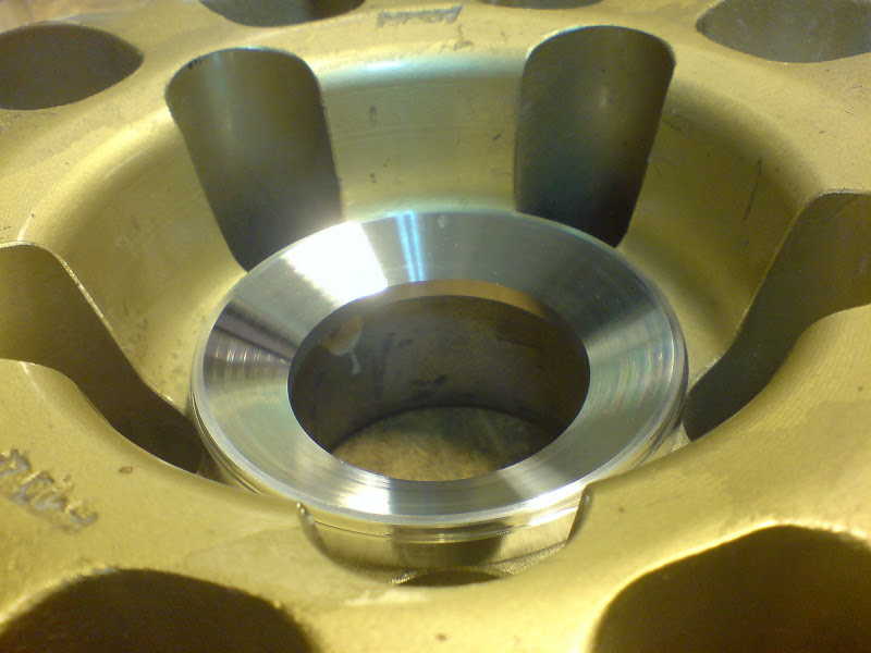
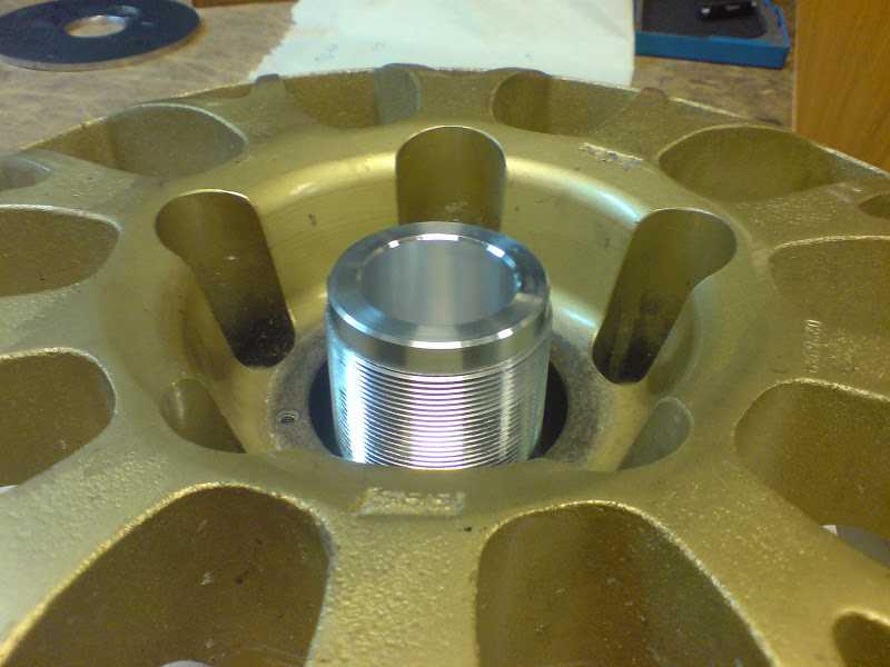
After one setup:
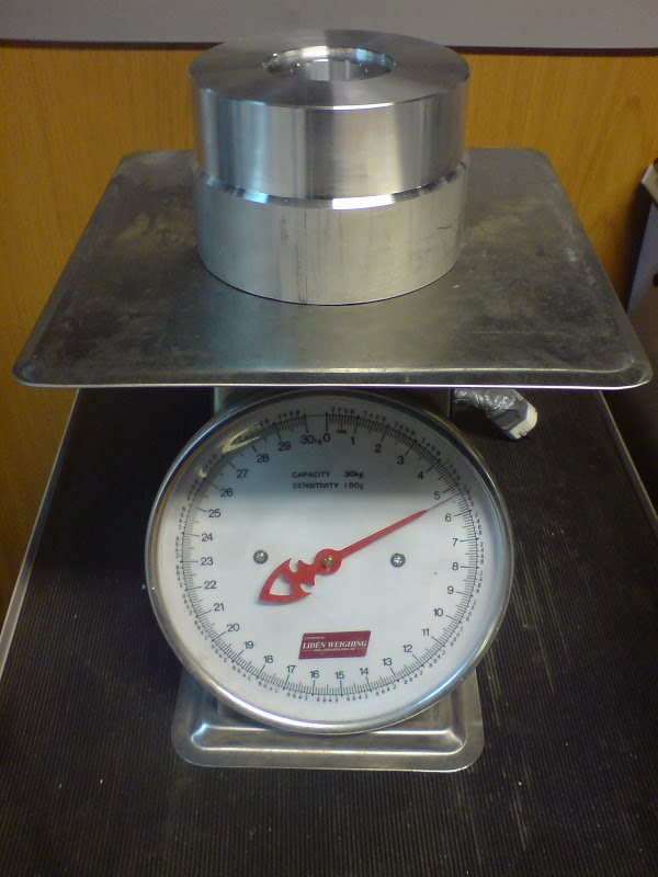
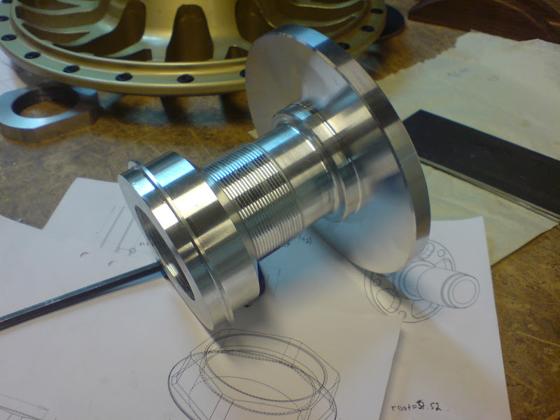
Backs all done:
Still need to do the front snouts, thread them, machine the bolt pattern in the backs and make the nuts.


 Brian Hobaugh SCCA National Tour June 2014
 First Hemi 'Cuda Convertible Ever Built
 Short clips: Goodguys Pleasanton autocross and pit videos


 :
:
 Linear Mode

