|
|

10-10-2017, 12:28 PM
|
|
Senior Member
|
|
Join Date: Mar 2014
Location: Plano, TX
Posts: 160
Thanks: 6
Thanked 67 Times in 33 Posts
|
|

continued from above
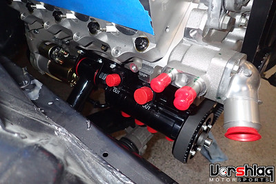 
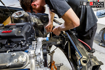
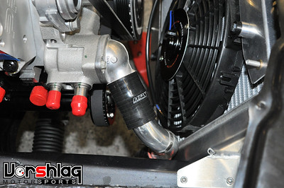
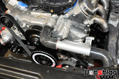
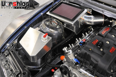
The dry sump pump was bolted on once the engine was in the car, to avoid smashing the shiny bits or fittings. The front drive accessories were already installed with the serpentine belt, then the cogged belt went onto the dry sump drive.
INTAKE MANIFOLD TESTING + REVERSE MOUNT
After talking to Koenig at HPR at length about intake manifolds, he kept stressing how important it was to use the right design for larger displacement (7L+) engines. To keep the engine from peaking too early, and losing all of the top end power, a shorter intake runner length (6.5-7" long) with enough cross section and throttle body size would help. There are many manifolds that have MUCH shorter runners (which kills mid range completely and rarely helps on top in an NA motor) and all too many with OEM style, LONG runners (which shuts off the top end). Not many in the middle...
 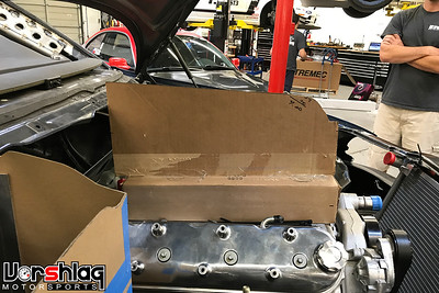
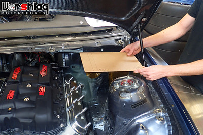
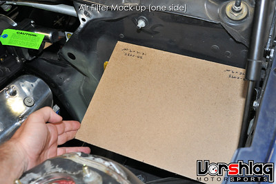
One of the few that have runner lengths and TB sizes in the range we wanted was the Holley Hi-Ram, which comes in cathedral, LS3 and LS7 style ports. With an optional 105mm throttle body opening and a 6.5" runner length (which is almost perfectly straight) the Hi-Ram could be worth another 30-50 whp up top. After I found the CAD print (top left) for this I asked Ryan to make a quick cardboard mock-up to check hood height. That was ridiculously too tall, and even flipped 180° to make it a "cowl breather" it was still many inches above the hood line (see above right). Like "making it hard to see" tall. We talked about making a custom intake but it was really time to "get going" so we picked the best OEM style intake on the market for the moment: the MSD Atomic.
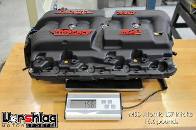 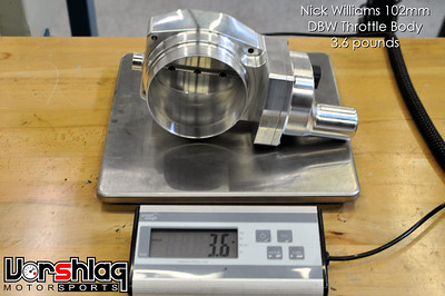
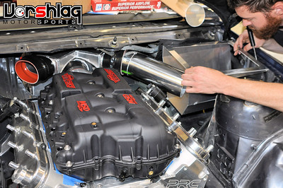
Of the OEM style crossover intakes the MSD Atomic LS7 intake has the "least long" runners at 8.5". The 103mm throttle body size is a bit unusual, as the common "big" sizes are 102 and 105mm. Then a lot of those options are cable operated - old school. To work seamlessly with a Motorsports traction control system we went with a Nick Williams 102mm DBW (Drive By Wire) throttle body.
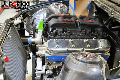 
This manifold bolted onto the HPR motor without any drama, and with the TB opening pointed forward it fit under the hood easily. But we're not going to keep this build easy... we wanted to flip the intake manifold 180° to keep the front clear for hood ducting (which we will show in a future installment) and to take in high pressure air at the base of the windshield (cowl). This "little change" unleashed a lot of custom fabrication work....
 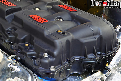
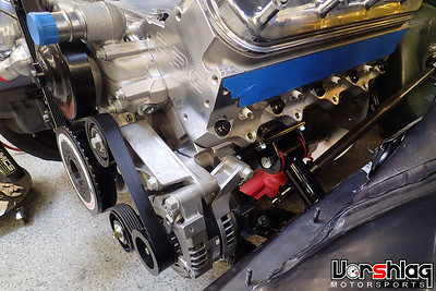
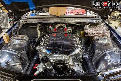
First of all, the OEM cast aluminum intake valley cover has an oil pressure riser cast into the back of the motor. You can see the red colored tip of this riser in the image above left. Most LS style intakes have a recessed edge to clear this at the back of the manifold, which can be seen in the image above right.
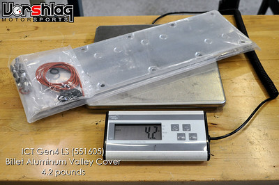 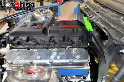
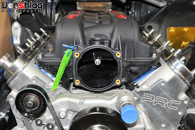
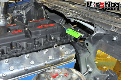
So to be able to flip this intake around we needed a flat valley cover with this oil pressure sensor riser deleted. This flat billet cover from ICT fit the bill and was an easy fix. This was installed and let us run the MSD Atomic flipped 180°. But as you can see above, there was no room at the firewall for the throttle body. I was hoping the TB might line up with the massive opening left by the cabin air filter structure, but this intake is too low to line up with that. Time to cut...
TWIN AIRBOX + COWL PLENUM FAB
To make this flipped intake fit we needed to cut the firewall up a little. Well.... OK, a lot.
This was the first stage of making a cowl induction intake system. You see with a mostly gutted dash and aftermarket HVAC box mounted elsewhere, and relocated master cylinder and no brake booster, all of a sudden we had a lot more real estate under the dash and at the firewall. So Jason, Ryan and I brain stormed an airbox mounted at the base of the windshield with a flat air filter element. Or two.
continued below

|
10-10-2017, 12:29 PM
|
|
Senior Member
|
|
Join Date: Mar 2014
Location: Plano, TX
Posts: 160
Thanks: 6
Thanked 67 Times in 33 Posts
|
|
continued from above
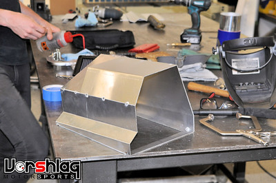
To maximize airbox volume we wanted to use a flat element air filter. Due to some space constraints in area, as well as off-the-shelf filter elements and their associated airflow limitations, we needed TWO air filter boxes. So we ordered those up while Ryan started building a plenum at the throttle body.
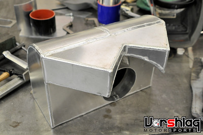 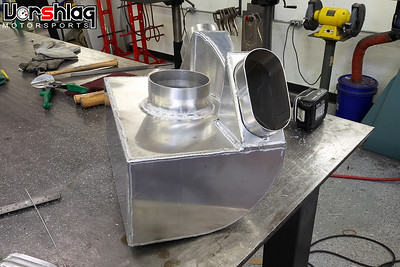
This box above will attach to the 102mm throttle body and create a certain amount of plenum volume for the engine to draw from. Air will enter through each of the 3" oval openings from the two air boxes. The constraints of the hood and engine placement limited the intakes to these 3" oval sizes.
 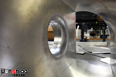
The 4" opening to the throttle body has a formed bell mouth and the box itself sits up under the dash. Ryan will make another fire proof enclosure to completely surround this and seal the engine compartment away from the passenger cabin/dash area (see below/left)
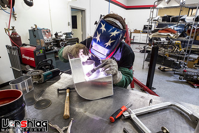
Twin air filter boxes were built, one for each side of the engine bay. They are somewhat mirror images but they do have some differences side to side, which are underneath.
 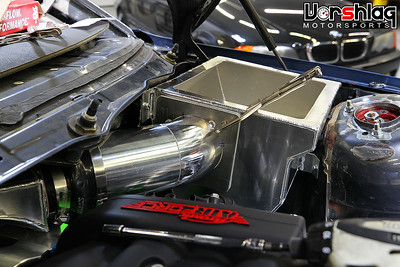
These air filter boxes mount to the chassis and then 3" tube and 3" silicone hose couplers route the "cold air" to the throttle body plenum box. Two K&N filters fit snugly into the tops of these air boxes and we will add some additional structure and seals that touch the bottom of the hood soon. These will mate up with two big holes we will cut in the hood to feed these filters.
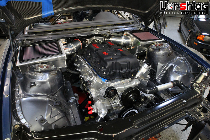
A couple of dozen hours went into the firewall clearancing, layout, plenum box fab and two air box fab work, but it should be more than able to supply this air to engine. This is being fed by a high pressure zone at the base of the windshield, which will help "at speed". And it all will help the Optima Design & Engineering scoring, too. Again, this is really being done to open up the front of the engine bay for hood ducting, to improve downforce on the splitter (soon) and improve cooling on the main radiator.
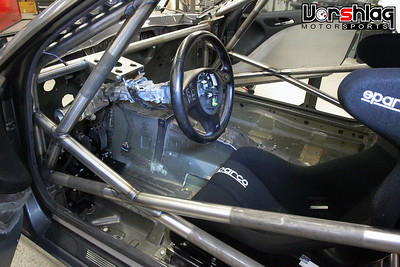
INTERIOR PANELS + STEERING WHEEL
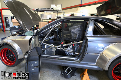
Up to this point we haven't shown much of the interior or our plans to make it safe yet pleasing to the eye. Gotta pass muster for D&E - they really punish gutted race cars in Optima, unless some real attempts at "an alternative interior" are made. Initially we just had roll up windows and custom door panels, but the rest was pretty Spartan. All business, no frills, and somewhat ugly. Time to spruce it up in there...
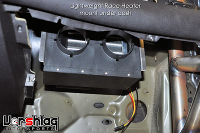
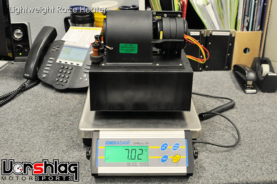
This interior was largely gutted when we found it, along with the air bags. The stock HVAC is also too heavy for a build like this, but we did add a compact heater core and blower motor unit that we've used on a number of race cars (just like on the tube frame 69 Camaro build). This 7 pound unit from Summit Racing is cost effective, compact, and much lighter than the OEM parts. This box was mounted under the dash on the passenger side and the outlets will be plumbed to the defroster vents soon. No air conditioning is going to be added - too heavy, and there is no place to drive an AC compressor with a 4 stage dry sump pump in the way.
  continued below
|
10-10-2017, 12:30 PM
|
|
Senior Member
|
|
Join Date: Mar 2014
Location: Plano, TX
Posts: 160
Thanks: 6
Thanked 67 Times in 33 Posts
|
|
continued from above
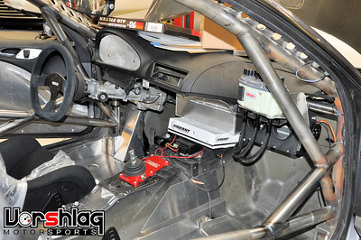
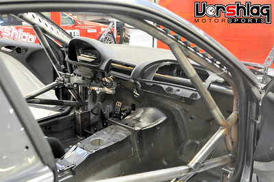
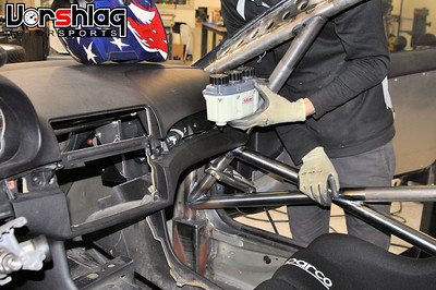
Another Tilton triple reservoir was purchased (also like on the 69 Camaro), which will feed the twin brake and single clutch master cylinder from the OBP floor mounted pedal box. This Tilton unit was mocked up and then mounted on the passenger side. Why have this in the passenger compartment? Three reasons. 1) Being visible to the driver makes it easy to see if fluid LEVELS drop during a session (indicates pad wear or a leak). 2) It makes it easy to fill the fluid levels, not buried down by the floor mounted pedals. 3) It keeps the bulk of the fluid away from heat in the engine bay.
 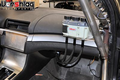
A few weeks later Ryan went back and made -4 AN braided lines for the reservoir and ran them to each master cylinder.
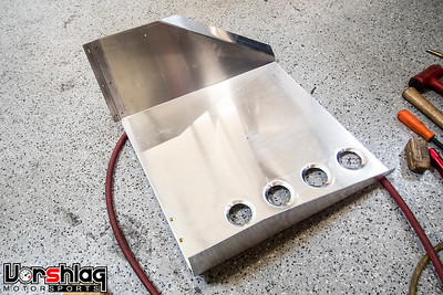 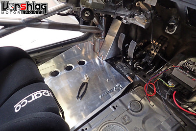
The spot your heel rests on at OBP pedal box was tied into a flat, false floor made of aluminum. A formed sheet aluminum dead pedal was also built and tied into the same section. These false floors are commonplace in race cars, and with the unusual non-flat floors of the BMW E46 they are pretty much a requirement if you remove the carpet and massive foam backing.
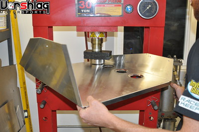 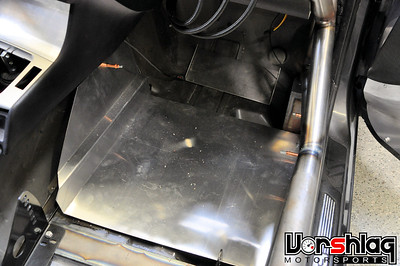
These were formed from 6061 sheet then dimple die holes were added on the press. We will add grip tape to the surfaces later, to keep your feet from sliding around if they get wet. The passenger side false floor was started but still needs some dimple die work.
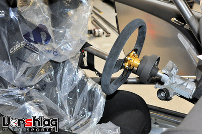 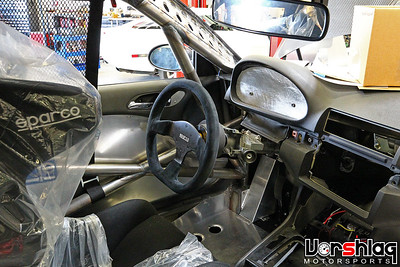
We couldn't leave the stock steering wheel in place so we ordered a Sparco wheel and Lifeline quick disconnect hub. This wheel fit the driver's position and has the right covering, and the Lifeline is the best quick disconnect on the market.
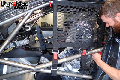 
Window nets might seem a bit extreme for a car with roll up windows, and it is unusual. But for a "street car" this M3 has an unusually high speed threshold, so the safety gear isn't being skimped anywhere. This mesh window net has great visibility but keeps "your arms and hands inside the ride at all times". We will add a center net later as well.
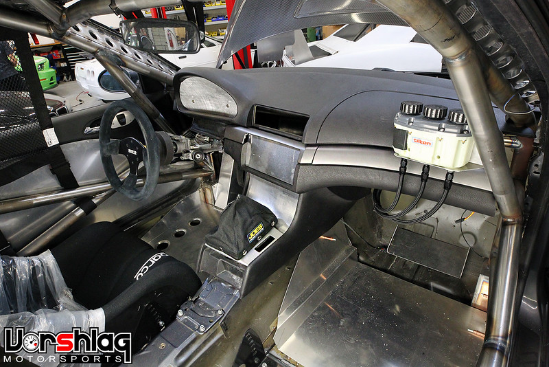
A lot of aluminum panels were built, which help fill holes in the dash where the radio, HVAC controls, and stock gauge cluster went. An AiM digital dash, possibly a rear view camera/LCD screen, and the fire pulls and main battery kill will go back into these places. A new set of "Titanium" OEM trim panels was ordered from BMW and installed to fill the gaps between the 2-pieces in the upper and lower dash sections. We will get a little crazier with interior panels and finishes before the car ever does an Optima event, but its already a lot better than the plain "gutted race car" look.
continued below
RADIATOR INSTALLED + HOSES BUILT
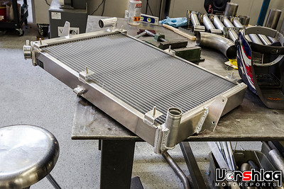
Spec'ing the radiator for this project took a little bit of work. This 7.7L motor would need the biggest radiator we could fit in front of the motor. We also wanted to duct the hood and "roll" the radiator forward at the top, so that meant we wouldn't be using an off-the-shelf aluminum E46 radiator.
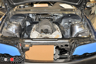 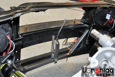
I asked Ryan to clear away anything in the way between the frame rails then measure for the widest core we could squeeze in there (27"). The center portion of the lower stamped piece of the radiator support was completely cut out. He then built a cardboard mock-up to verify the max height core possible. Then we had to spec the hose outlets for an LS engine accessory layout, with the suction on the passenger side and water pump outlet on the driver's side. The goal was to shove as much of the radiator forward under the radiator support as possible without running into the front nose or crash beam. Unfortunately the headlights became a limiting factor for forward roll of the radiator, so the bottom of the core was pulled back closer to the balancer, to gain more angle and radiator height room.
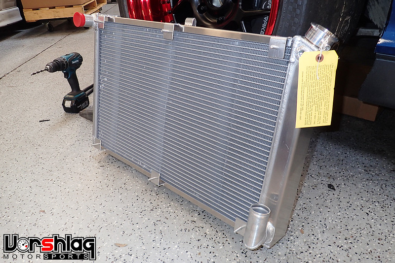
The mock-ups and other specs led us to a BeCool 60229 radiator, which was custom ordered back in May. It took a while to be built and shipped here but when it arrived Ryan made brackets to mount it in the layout we wanted.
continued below
|
10-10-2017, 12:52 PM
|
|
Senior Member
|
|
Join Date: Mar 2014
Location: Plano, TX
Posts: 160
Thanks: 6
Thanked 67 Times in 33 Posts
|
|
continued from above
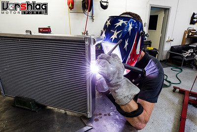
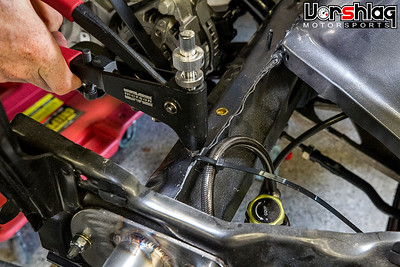
After the motor was installed with the balancer in place the BeCool unit was mocked-up in the final rolled forward position. Templates for brackets were cut and transferred to aluminum plate, which were cut, drilled and welded to the side tanks of the radiator.
The brackets were drilled for mounting holes that allowed them to bolt to the frame rail. Nutserts were drilled and installed into the frame rails for these mounting bolts, shown below. These initial mounts are bolted directly to the frame but about 1" of room was left to add some isolators. We will do this when we build the ducting, as well as possibly add a secondary set of mounts at the top and/or bottom.
More calculations were done and the slimmest, highest flowing pair of fans that covered the most area of the core were ordered.
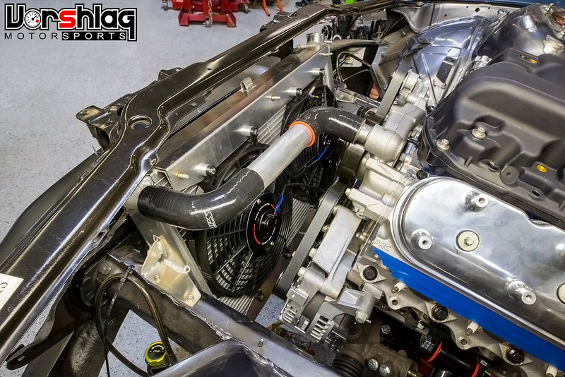
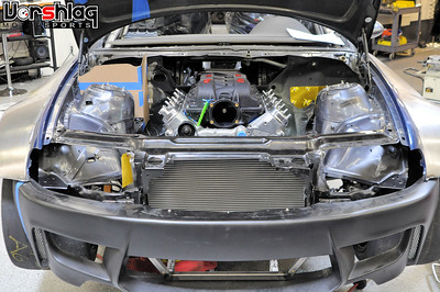
These Mishimoto Slim 12" electric fans (MMFAN-12) each flow 1150 cfm. A bracket was built along the top and bottom to mount them close to the radiator core. There are more powerful fans in 12" but they were all thicker and could run into parts of the engine.
Some custom radiator hoses were built from HPS silicone hose bends and some mandrel bent and straight aluminum tubing. The front of the radiator core will be ducted to the gill openings at the front and to the hood opening behind it - we will show this later in the build.
WANGIMUS MAXIMUS
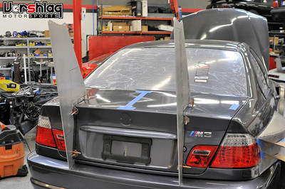
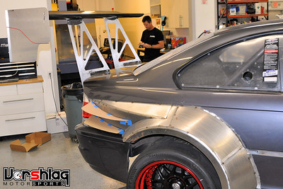
"Big Downforce" is part of the "Bigger is Better" mentality we are applying to many aspects of this build. Of course a giant rear wing was ordered from AJ Hartman Aero - a full 72" wide and with his longest 14" cord.
We have installed plenty of rear wings but on a car that could see speeds in excess of 180 mph, it needed to be a bit overbuilt.
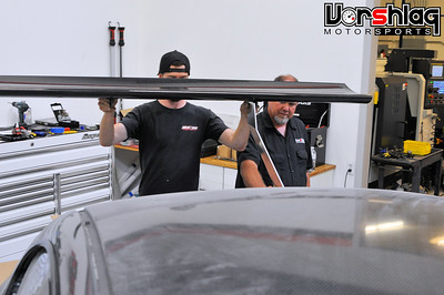 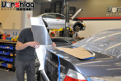
After deciding where the uprights would be (and thus the under-mount saddles) we ordered the wing. When it was delivered we played with mounting locations, getting the element where it could "do the most work" - way up high and far back - then Ryan made cardboard mock-ups, which progressed into plate aluminum versions. We had thought about a bent upright, but that was quickly abandoned in mock-up.
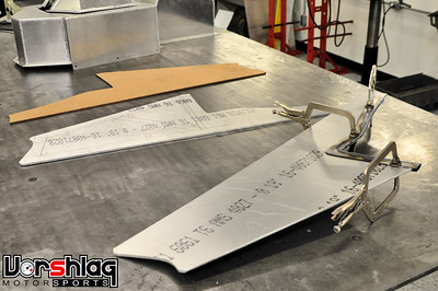 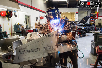
We settled on this flat design that would be gripped with a steel U-shaped lower bracket, that could then be bolted to the trunk.
continued below
|
10-10-2017, 12:52 PM
|
|
Senior Member
|
|
Join Date: Mar 2014
Location: Plano, TX
Posts: 160
Thanks: 6
Thanked 67 Times in 33 Posts
|
|
continued from above
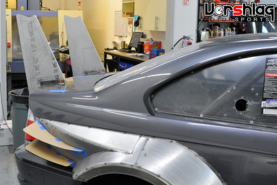 
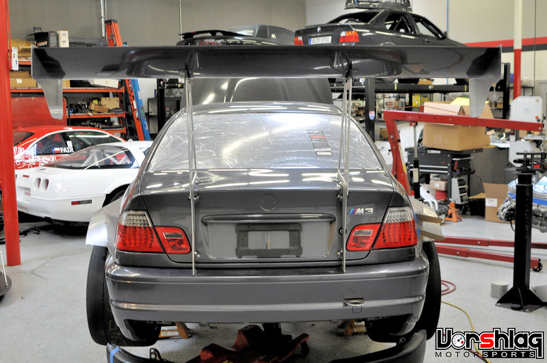
Once these were cut, brackets made, and they were test fit the lower steel brackets were bolted to the trunk lid. The OEM steel trunk lid is very strong but we also extended the lower portion down to touch an adjustable perch onto the tubular rear bumper beam. We will made a "saddle" that looks prettier before paint, but this puts much of the vertical load into this beam and less on the trunk structure.
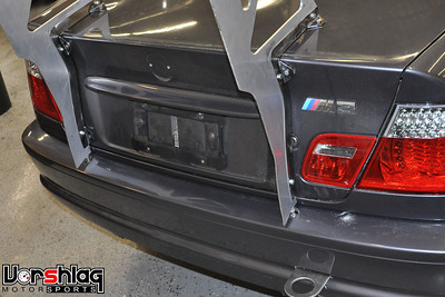 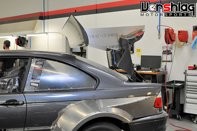
The trunk can swing open fully and the wing element clears the roof easily. This is due to the rear biased, high mounted placement of the wing element.
 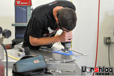
The "windows" above were cut out by hand - using a hole saw and jig saw. There are much faster ways to do this using robots... a CNC water jet or plasma table makes this much faster but we didn't have the time to transfer all of this into CAD then run use someone's table. Yes, I need to buy the shop a CNC plasma table...
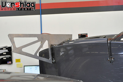 
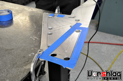
The lightened uprights were completed and then endplate designs were tested and tweaked...

Some details on the image above (red line) have been completed but its the best picture I have of the finish wing currently.
Quote:
|
GTL class - any spoiler or wing configuration with a maximum of 6 tall from its highest mounting point or a maximum height of 4 above the lowest point of the rear window, whichever is less. The maximum width of the spoiler/wing must be no wider than the original panels of the car and must not extend more than 6 inches past the furthest point of the rear of the car. No wing may exceed 8 inches in chord length (front to back) at any point.
|
We know that the 2017 aero rules for Optima are pretty limited and we will create a separate aero package for that series. We will use a carbon fiber trunk to mount that Optima aero package, which would make for a simple "trunk swap" to be legal for that series. The big wing would be used in NASA and other events.
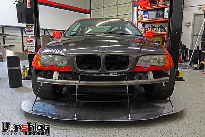 
A massive splitter, the soon-to-be ducted hood, and some other bits will make up the front aero. We just made this front splitter for my 330, but the one for the M3 will be bigger in every way.
WHAT'S NEXT?
Wow, that was a lot of ground to cover, and I didn't get to everything that's completed. Next time I will show the twin fire systems, chassis wiring that has begun, the fuel system components that have been arriving, and the Motec M1 + wiring harness which is being built by our friends at G-Speed.
The rear differential is now assembled with a Wavetrac LSD and Ford Racing gears, the exhaust headers should be wrapped up soon, and then a driveshaft and exhaust can be built after that is in place. The custom coolant reservoir was just completed, heater hose plumbing has begun, and Ryan is spec'ing out the oil hoses next.
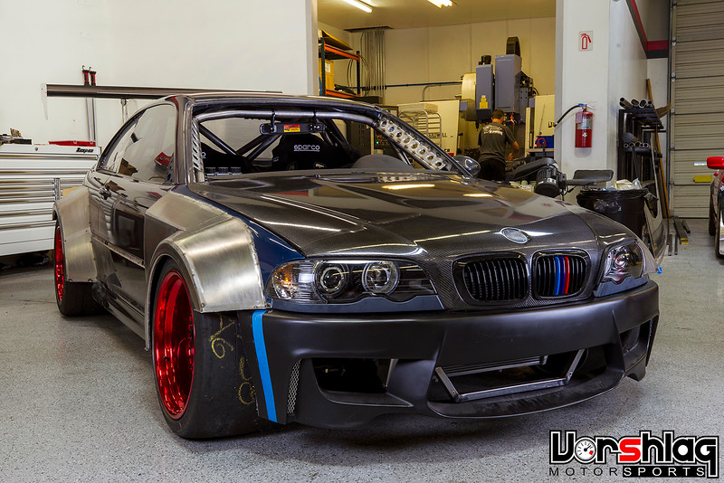
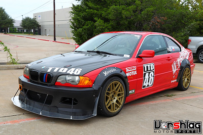
This is what the M3 looks like today. Tune in next time to see more progress!
Thanks for reading,
__________________
Terry Fair @ Vorshlag Motorsports
|
10-10-2017, 01:14 PM
|
 |
Senior Member
|
|
Join Date: Feb 2005
Location: TX
Posts: 266
Thanks: 0
Thanked 0 Times in 0 Posts
|
|
Reeeeaaaaalllly makes me want to get an E46 M3!! Nice work!
__________________
Kyle
|
10-10-2017, 02:28 PM
|
|
Senior Member
|
|
Join Date: Apr 2014
Location: ATL
Posts: 748
Thanks: 11
Thanked 58 Times in 36 Posts
|
|
One just cannot take one's eyes away from the "Massacre." I applaud your creativity on this build, as it's both modern, in terms of materials and technology, and classic in terms of the skills (and positive hope) applied to getting them to work. This is the kind of car people (with or without cars) come to see in action. On this level, you guys are definitely winning!
Thank you for your efforts in comprehensively posting. Whether or not things work out perfectly with the car or the manufacturing/workmanship/spitballing is not the point. Ideas can still be awesome and not work perfectly at a particular time, but it's awesome to see the application (and effort). If things do work perfectly (happens all the time, right?), all the better. Thanks for sharing another awesomely crazy build with us! 
If magazines had stuff like this, the value of paper (print media) could go up again . . .
|
10-10-2017, 03:16 PM
|
 |
Moderator
|
|
Join Date: Sep 2005
Location: NorCal
Posts: 9,180
Thanks: 58
Thanked 158 Times in 104 Posts
|
|
Just outstanding.
__________________
2004 NASA AIX Mustang LS2 #14
1964 Lincoln Continental
2014 4 tap Keezer
|
10-10-2017, 03:42 PM
|
|
Senior Member
|
|
Join Date: Feb 2005
Location: Dallas TX
Posts: 709
Thanks: 87
Thanked 252 Times in 170 Posts
|
|
Quote:
Originally Posted by rustomatic

One just cannot take one's eyes away from the "Massacre." I applaud your creativity on this build, as it's both modern, in terms of materials and technology, and classic in terms of the skills (and positive hope) applied to getting them to work. This is the kind of car people (with or without cars) come to see in action. On this level, you guys are definitely winning!
Thank you for your efforts in comprehensively posting. Whether or not things work out perfectly with the car or the manufacturing/workmanship/spitballing is not the point. Ideas can still be awesome and not work perfectly at a particular time, but it's awesome to see the application (and effort). If things do work perfectly (happens all the time, right?), all the better. Thanks for sharing another awesomely crazy build with us!
If magazines had stuff like this, the value of paper (print media) could go up again . . . |
^^This! ^^
|
10-11-2017, 01:23 AM
|
 |
Senior Member
|
|
Join Date: Nov 2014
Location: Melbourne, Australia
Posts: 261
Thanks: 106
Thanked 99 Times in 71 Posts
|
|
Technology and common sense......
^^^^what they said^^^^
....and thanks for the professional pics and text. 
__________________
Jim Grant
Melbourne, Australia
(Dual citizen)
|
 Posting Rules
|
You may not post new threads
You may not post replies
You may not post attachments
You may not edit your posts
HTML code is Off
|
|
|
All times are GMT -7. The time now is 05:15 PM.
|


 Brian Hobaugh SCCA National Tour June 2014
 First Hemi 'Cuda Convertible Ever Built
 Short clips: Goodguys Pleasanton autocross and pit videos


 Linear Mode
