Well, I finally got all the undercoat scraped of the bottom of the car. What a horrible job that was. My garage floor is a wreck!
With that done, though I had time to work a bit on the assembly of the steering system last night.
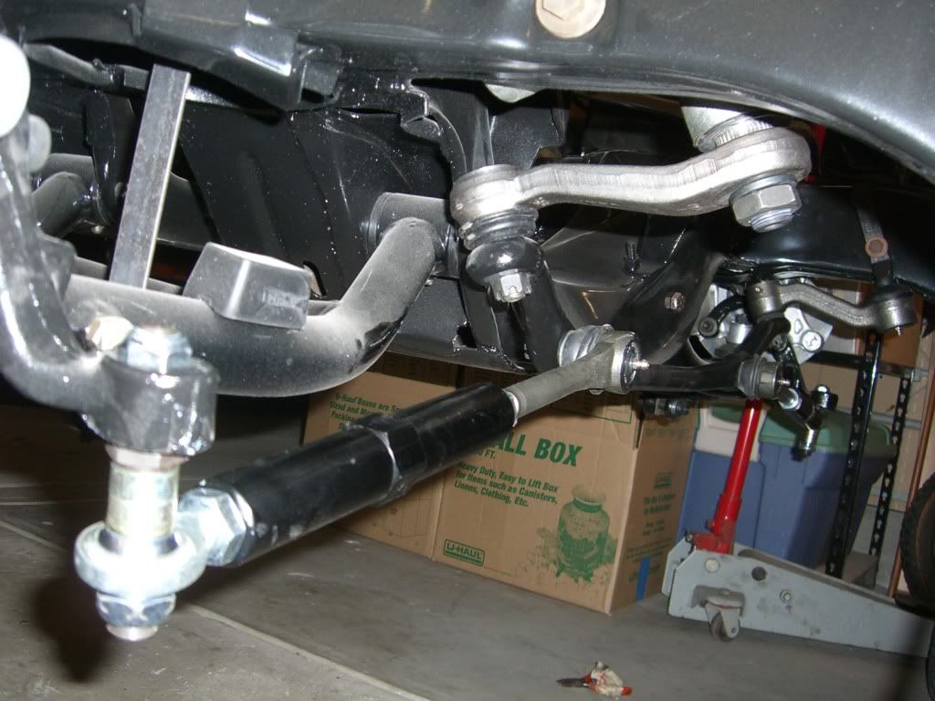
Started with the idler arm and steering box. Found out from David Pozzi that there can be some bind with the idler if the drag link is not installed with the idler arm/subframe bolts loose. He's right. I didn't loosen the bolts before I put the drag link in and....Yup. Sure enough. Bound up like a colon full of cheddar cheese.
Not to self and anyone else with a Camaro: David Pozzi knows his stuff. Listen to him.


The steering box is an ATS 670 unit. These are built for ATS by Tom Lee. I've had the pleasure of speaking to him on the phone. He struck me as one of those eccentric old wizards. When he isn't building super high-zoot stuff for teams in NASCAR, ALMS and others he works on stuff like this for us mortals.
The ATS/LEE 670 boxes are initially built on an assembly line with normal production tolerances. ATS's spec for the Lee box requires that every brand new unit is completely taken apart, re-honed, blueprinted, re-valved, dyno tested, magna-fluxed, and finished in some kind plating. They used to use a really sexy looking cadmium, but the CA EPA (nazis) rules are such that they are now using zinc. Still a good looking unit, but not as cool as the cad plating. These are race proven precision boxes, built exclusively for ATS. I don't know all the details of what Lee does with the valves, but I've driven a car with one of these in it, and it is by far the best feeling recric-ball steering gear I've ever felt. Better than a lot of rack/pinion setups in terms of feel.
Tyler, feel free to expand on this a bit.
Next up is the tie rod assemblies. The inner is a run of the mill Moog unit. The outer though is kinda neat. Baer brakes makes these things called "Baer Trackers" (a bit silly) but cool. Big honkin high offset rod end connected to a 1-3/16" dia aluminum coupler that threads directly onto the inner tie rod. The Baer Trackers provide the capability to adjust out any remaining bump-steer from the system by swapping the cad-plated shims (see photo) either above or below (or both in differential amounts) the rod end. A bit bulky, but still lighter than the traditional tie rod it replaces.

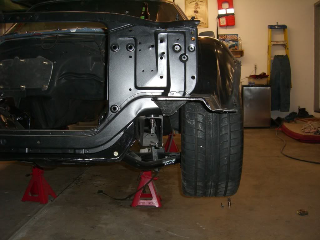
So with those bits installed I can see about mocking up some of my clearances.

That's a 275x40x17 tire on a borrowed 17x9 vette rim. The offset of the wheel is nothing like what I'm going to run, but it gives me something to calculate from.
....and it looks like I have some "cipherin" to do here.

With the steering arm bolted directly to the spindle, the tie rod assembly set at the OE length and the max offset on the bump steer adjuster the rod end crashes with the inner flange of the wheel.
Spoke with Tyler about it this morning, and the solution is not that big of a deal. I can space the steering arm inboard a bit, shorten the tie rod assembly accordingly, and the wheel spacer I will need to run to clear the Wilwood 6-pot brakes will move the wheel outboard enough to provide the required clearance.
It's always something isn't it?
Not to worry though. With the Speed-Tech control arms adjustable steering stop feature I'll be able to make the above modifications without much negative impact on total available steering angle. SWEET!


