|
|

12-31-2015, 09:11 AM
|
|
Senior Member
|
|
Join Date: Mar 2014
Location: Plano, TX
Posts: 160
Thanks: 6
Thanked 67 Times in 33 Posts
|
|

continued from above

Some mounting bungs were also machined for the transmission crossmember, and then those were tacked to the frame for a proper crossmember mount.

The holes were drilled in the square tubular front subframe to mount the weld-in bungs. More structure is going to tie all of the subframe together at a later day, and it won't be left "open ended" like this.

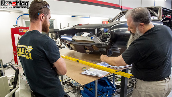
A look from underneath shows the mounting bungs tack welded in place and the new Woodward steering rack finally mounted to the chassis. From here it was time to make the steering shaft, or at least mock-up most of it, before header tubes were snaked around that.

Another one of Brad's "glamour shots" of the rack mounted in place. I've never seen a steering rack that looked so damned good. Weird.

I snapped a quick and ugly shot here to show that the valve covers were installed an an ignition coil and spark plug wire were in place. This coil and plug wire was moved from port to port to make sure each primary tube gave clearance for the plug wire.
CUSTOM EXHAUST HEADERS - LEFT BANK
Now that the steering rack was in place, and the steering shaft built (and attached at one end) and mocked in place, the driver's side exhaust header could be laid out and built.

Back to the Ice Engine Works kit, which was mocked-up up on the exhaust flange. Several iterations of each primary tube could be quickly tested before cutting any metal.

Once the routing looked good in plastic each Ice tube model can be removed and replicated in stainless steel bends. Lots of time but its worth it for one-off or prototype header development.

Snaking around the steering shaft is always tricky, so the driver's side header on LHD cars usually takes a bit more time. The steering shaft is a 2-piece collapsing design using stainless 3/4" DD inner bar that slides inside 1" hollow DD tubing, with Flaming River needle bearing U-joints at both ends.

At this point all of the ignition coils and plug wires were attached to verify primary room and most of the tubing layout is complete. In the image below you can see the convoluted design of the transmission crossmember, which is necessary due to the very low mounting height of the engine (dry sump oil pan) and transmission, flat bottom nature of the floorpan, and the need to tuck two 3" main exhaust pipes above the floor.

The starter is in place here and you can see how the collectors come back into the custom transmission tunnel. The driver's side was the constraint on primary length, as the external shifter has levers and rods that reduce clearance on that side. The shortest primary is about 26" long, which will is appropriate for this motor, and still considered full length.
RADIATOR MOUNTING
To check hood and sheet metal clearances the entire front end was installed again.

The customer brought us a custom C&R Radiator made to bolt into a 69 Camaro. It was a beautiful 2-pass heat exchanger that had an integral oil cooler and power steering cooler and included a plastic fan shroud . This would be a great package for a street driven car, but this is more of a track beast.

The other problem is the C&R that the owner provided (above left) was too wide to fit the frame rail width on the new custom frame. The width of the new frame was dictated by other factors (wheel size/offset, C6 spindles, C6 control arms, camber range needed) so this nice C&R radiator would have to be changed. We used the Griffin (above right) stock car style radiator that would soon go into my C4 Corvette (Project #DangerZone) as a mock-up for the 69 Camaro.
continued below

|
12-31-2015, 09:12 AM
|
|
Senior Member
|
|
Join Date: Mar 2014
Location: Plano, TX
Posts: 160
Thanks: 6
Thanked 67 Times in 33 Posts
|
|
continued from above

The narrower width of the Griffin worked perfectly. We had a ducted hood and custom front grill inlet idea already in mind so a severely forward canted radiator angle was what was tested. With this data another "basic" C&R Radiator was ordered, this time without the integral oil and power steering coolers.

Once the new C&R arrived Ryan began to build the brackets necessary to mount it to the frame. Some of this is square tubing, the rest is flat sheet with dimple die holes to give it strength and reduce mass.

The tubular front mounting bar for the splitter and nose was also built, but I will talk more about that next time. Here you can see the new C&R radiator in its final mounting location and tilt. Since it is sitting this low we will be able to block off the upper grill completely (reducing drag) and make a inlet duct box for the lower grill to feed the various heat exchangers, which will then vent out of the hood. This C&R core has a -20 AN fitting for the upper hose connection, which you can see above. The lower "hose nipple" would later be cut off and another -20 AN male fitting welded in place. This car will have all pressurized systems plumbed with threaded fittings, throughout, even coolant lines.

It is always a good idea to protect the fins of the heat exchangers during fabrication. We wrap card board around them to prevent damage to the delicate fins when these go in and out, get mocked up in various ways, etc. You might see a sneak peak of a splined 3-piece swaybar in the images above, but I'll talk about that more later, when the splined ends and endlinks are fitted.
CUSTOM DRIVESHAFT
The custom 3.5" aluminum driveshaft was spec'd out by Jason and Ryan and ordered a week earlier.

After that arrived it was slid in place to the output shaft of the G-Force trans and bolted to the axle flange on the Ford 9" input flange. It fit perfectly and looked great, and we've ordered more shafts from this supplier since.
 WHAT'S NEXT?
More fabrication was completed and more parts were ordered and/or installed in September including more front tubing and structure, custom accessory brackets, and more.

And in October we're working on front grill/bumper, custom aero with a dual plane splitter, custom front sheet metal and flares/canards, front brake ducting, additional heat exchangers, and hood ducting.

Until next time,
__________________
Terry Fair @ Vorshlag Motorsports
|
12-31-2015, 09:13 AM
|
|
Senior Member
|
|
Join Date: Mar 2014
Location: Plano, TX
Posts: 160
Thanks: 6
Thanked 67 Times in 33 Posts
|
|
Project Update December 6th, 2015: This forum post update covers work we did to the 69 Camaro in September of 2015. This included LED tail light fitting, radiator work, cooling fan mounting, custom splined swaybar mounting, as well as custom engine accessory drive brackets that had to be designed and fabricated. This chunk of 69 Camaro work was all done in a VERY busy month for Vorshlag's race shop, too.
LED TAIL LIGHT INSTALL
The original tail light assemblies were 46 years old, worn, and showing their age (see below). These were made for old style incandescent light bulbs and the owner wanted something that looked original but had a more modern function underneath - which is pretty much the theme of this whole build, so its natural that this thinking went into the lighting as well. Since this car could be made legal for limited road use. Also, street legality makes it possible to attend events like Optima and possibly even run in SCCA's CAM class, so it needs to have functional head lights, brake lights, turn signals and wipers. That aside, it needs to at least have brake lights for any track events.

These "little street car things" can be time consuming additional work to high end, tube framed, serious aero, race car build like this, but its nothing we cannot tackle. Texas has a rolling 25 year exemption for annual emission inspection, so a 46 year old car like this can be inspected and road legal for a mere $14 "safety only" inspection - where they check the horn, lights, and turn signals only. Next year this exemption applies up to the 1992 model year (aka: now a 1992 model car is a "Classic"), which gives me some evil ideas on another car I own (many of you will figure out what and why, quickly).

We made our $2011 GRM Challenge winning race car (above and below) pass the Texas safety inspection checks with only a few small changes, as it was a 1986 model when we did this back in 2012. Amber LED turn signal strips were added up front, since the E36 grafted nose didn't have room for the OEM housings. After it got the legit inspection and registration stickers (and insurance) I drove it to Cars & Coffee type events (on "DOT legal" Hoosiers) without the need to trailer it.
And for those that doubt that an LS-powered RWD car with an OEM tub can be built with big wheels and tires (18x11) and still hit the 2500 pound goal we have guesstimated for this 69 Camaro, well this was our all OEM steel and glass equipped, wide bodied BMW E30 with an aluminum LS V8 on the scales at 2534 pounds, 100% street legal. Granted, this only had a 4-point roll bar, but it had a full interior and dash. And please ignore the fit and finish on that thing - it was built for $2010 in parts for the GRM event (the 18x11 CCWs and ASTs we sold it with were outside of that budget).

This Camaro is pretty overbuilt compared to this E30, so it might be as much as 100-200 pounds heavier, but also has all aluminum front bodywork, fiberglass doors, and most of the unibody structure is gone. It won't be some 3300 pound, pavement crushing Pro Tourer, trust me. We will weigh the heck out of this car when its off the frame table (soon!).

So the 69 Camaro needs functional tail lights, turn signals, and headlights to be street "legal". We discussed a number of options with the owner, including some rather modern looking billet aluminum tail light assemblies with integral LED lighting, like the ones below. But the owner wanted to stay with the classic housings and just use LED lighting underneath, as unobtrusively as possible.

Then we looked at LED retrofit kits for 69 Camaro housings, like the image below, and that's what we all agreed to use. This was coupled with a flasher unit made for LEDs, and the total on these parts was around $250 for a quality brand that had good reviews by users.

Next up was ordering a brand new pair of OEM style 69 Camaro tail light assemblies, then Ryan added the LED lighting arrays to the housings. There is a tedious bit of work involved to do that but he got them installed and wired up to a pair of harness connectors for each housing.

These are mounted in the back panel and ready for wiring, which is still several weeks away. Better than looking at two holes in the rear bodywork.

These look fairly "plain jane" now but when you power them up they are BRIGHT, so that should go well with the LED headlight assemblies as well...

These 7" LED "truck light" style round bulb replacements will replace the $8 stock style round bulbs we have in the car now for mock-up. We will install these later in the build - don't want to damage them, as they cost a bit more than $8 each. 

That's a bit of a sneak peak at where we were in late November and shows the airbox and small tubular bumper mounting structure used to mount the splitter struts, headlights, fenders, and more. We'll get to that further in this thread.
continued below
|
12-31-2015, 09:15 AM
|
|
Senior Member
|
|
Join Date: Mar 2014
Location: Plano, TX
Posts: 160
Thanks: 6
Thanked 67 Times in 33 Posts
|
|
continued from above
RADIATOR OUTLET FABRICATION
This is one of those projects where plumbing becomes critical, as the motor has a dry sump and we're adding oil coolers for the engine, power steering, and more. When we build any race car plumbing we go to AN style (37° inverted flare) fittings and the appropriate lines for the pressure and fluid being used.

The C&R radiator we spec'd to fit the frame rail width and height we needed at the layback angle we wanted was available with a -20 AN fitting welded to the upper (inlet) hose connection. But the lower (outlet) was a normal nipple made for a clamped rubber hose fitting.

The C&R's lower hose nipple was cut off and shortened, then an additional ARP -20 AN aluminum weld bung was sourced, mocked-up, and welded in place for the lower outlet.

A billet thermostat housing was added to the water pump outlet in a matching -20 AN size. We still need to adapt the upper radiator hose mount at the water pump and the heater hoses, then all of the coolant connections can be matching AN fittings. Is this 100% necessary? No, but it is commonly done on dedicated race cars, which this car has many aspects of.
FAN BRACKETS + SPLINED FRONT SWAYBAR MOUNTING
These two items seem pretty unrelated, but the packaging of the radiator and front swaybar were actually done hand-in-hand, earlier in the build. The placement of the swaybar is limited by several things - like the approach paths for the splined "ends" that attach to endlinks and ultimately the C6 lower front control arms, and often by the crossmember or engine. We had long lost hope for an off-the-shelf one-piece swaybar solution, so as most race builds do we went with a circle-track style splined tubular bar setup.

These come in a variety of lengths, diameters, and stiffnesses - usually too stiff for street car grip levels, but with 315 Hoosier A6 tires up front this car will have plenty of grip for track use. You always hope for there to be plenty of room to mount a straight swaybar like this, and with the 18" setback of the engine we had ample space in front of the engine. But it was apparent that the ducting for the exhaust side of the radiator would be right where the anti-swaybar needed to go. We've seen some kooky placements of swaybars, like at the top of the engine bay with with 30" long endlinks, but we chose to keep the endlinks manageable and the splined ends within reason. So we mounted the swaybar to grease-able bearing mounts shown above.

So with the swaybar mounted the dual fan setup from the existing C&R "bolt-in 69 Camaro radiator/fan combo" were mounted to the new C&R core. Ryan had mocked the fans up before the final location for the swaybar was picked. He made templates for aluminum bracketry in cardboard before transferring it to aluminum sheet.
 You can see above why the fan brackets and swaybar were done at the same time - fighting for space
The aluminum sheet was cut in the sheer and bandsaw, then bent in the brake, then nut-serts were added for the fans housings to bolt to. The finished aluminum brackets were then riveted to the exposed flanges on the C&R radiator, and the fan assembly was then bolted to the new brackets. It all fits tight to the fins (but not touching), leaves little of the radiator core expose beyond the plastic shroud from the fans, and could work well for street use if needed.
With the swaybar location locked down Ryan could then specify the splined aluminum ends to order as well as pick up the end link parts needed to tie the bar into the control arms. I'll show that in a later update, as it was done a couple of weeks later than this.
CUSTOM ACCESSORY BRACKETS
Early on in this build we were all concerned with the brackets used to mount the accessories to this LS3 based dry sump engine. The alternator on the car when it came here was not the OEM LS3 unit, but a smaller aftermarket unit rated at lower amperage. Somebody had also hacked up this "smaller" aftermarket unit beyond recognition - trying to make it fit the OEM bracket and the previous front end. Ryan found a racing style, smaller diameter alternator that was rated at the appropriate amperage so this needed to be mounted to the engine. The power steering pump was mounted to the same OEM cast aluminum bracket that wasn't going to work, so this needed to be re-mounted as well.

We had narrowed the front frame rails by about 2" from the "kit" front end the car came in here with, making space for both of these accessories more of an issue. There wasn't an of off-the-shelf bracket setup we could find that would re-use the various pulleys and engine accessories - including the balancer and dry sump pump drive - without some custom bracketry. We discussed this with the customer before proceeding, and looked at all manner of off-the-shelf LS bracket options, both factory and aftermarket. None seemed to fit the confines of this frame and hood line.
continued below
|
12-31-2015, 09:16 AM
|
|
Senior Member
|
|
Join Date: Mar 2014
Location: Plano, TX
Posts: 160
Thanks: 6
Thanked 67 Times in 33 Posts
|
|
continued from above

So Ryan began designing a custom, complicated assembly of brackets on the driver's side of the block to mount the power steering pump, the new small alternator, and an idler pulley.

He made templates from cardboard, then more durable ones from MDF, which helped him perfect the patterns before going into CAD.

The power steering pump is at the bottom left of the engine bay....

...and the alternator is at the top on the same side. This was needed to clear the tubular structure of the front control arm mounts and narrower frame rails - which were needed to get the proper suspension geometry and camber settings for the existing wheels and tires the customer wanted to keep.

After the templates were perfected in CAD they were printed out in 1:1 scale, trans transferred to aluminum plate, and cut out on the vertical band saw.

There were several aluminum plates, machined spacers and various hardware used to tie it all together and mount everything to the block and cylinder heads.

This is what the assembly looked like off the car with the alternator and power steering pump attached (foreground) along with the cast bracket it was replacing (background). We didn't use computer simulations and FEA to remove every ounce from the bracket assembly, as some have asked about darned near everything we've done along the way. That just isn't practical for this type of one-off track car build. Sure, if this was a $500K, full-effort, pro race car, then maybe. Instead the assembly was built with rugged materials and hardware using experience and forethought, and it should make for a rigid set of mounts for these accessories.

This is what the bracket looked like attached to the motor, along with the idler at the bottom - as shown above. The brackets were all hand cut, edges were ground and sanded, and we will anodize these parts when the car comes apart for paint. Clear or black, maybe even a color? Its up to the customer and won't cost much. Leaving them raw is an option but they will get water spots and such that have to be scotch-brited out.

Here we have the brackets and accessories installed with the correct length serpentine belt installed (we tried a few sizes to find the best fit). There is "good wrap" on the crank pulley, alternator, both idlers, and the water pump and power steering pulleys.

It was a dozen hours of measuring, design, and fabrication work but this assembly is critical to keeping the belt aligned (to avoid slinging the belts off at high RPMs) and to keep all of the accessories mounted firmly to the engine, nestled between the narrow frame rails. Losing a belt can lead to loss of electrical power, coolant flow, and if you are really unlucky, a flying serpentine belt can kick the cogged belt off the dry sump oil pump drive - and that can get costly in a hurry.
WHAT'S NEXT?
That was September's work, which wasn't exactly super sexy aero bits or big suspension work, but it was all necessary to move forward.
Next time we will finally cover the splitter + new lower valance design + the hood duct layouts. We sent a lot of images to the customer back and forth before we cut metal, and even sourced a flat hood to test hood ducts without the raised cowl hood restrictions.

Ryan was working on some other projects and on vacation for a week that month, so this was all of the September work completed on the 69 Camaro.
We also had the LS-FRS in the shop for a bit of follow up work, and took a bone stock 2003 NB Miata to a fully caged and prepped track car in 3 weeks, plus did more work on the LS Miata and other cars - all during September. It was a very busy month in the shop, for sure.
More next time,
__________________
Terry Fair @ Vorshlag Motorsports
|
12-31-2015, 09:36 AM
|
 |
Moderator
|
|
Join Date: Sep 2005
Location: NorCal
Posts: 9,180
Thanks: 58
Thanked 158 Times in 104 Posts
|
|
Glad to see you posting here Terry. Love your detailed write ups of the work you guys do.
__________________
2004 NASA AIX Mustang LS2 #14
1964 Lincoln Continental
2014 4 tap Keezer
|
12-31-2015, 12:06 PM
|
 |
Senior Member
|
|
Join Date: Dec 2009
Posts: 5,044
Thanks: 6
Thanked 9 Times in 6 Posts
|
|
Always fun to read your project posts Terry!
Quote:
Originally Posted by Fair

A moderator here (Flash68) follows this build on another forum and today he asked me to port the thread over to Lateral-G, so here it is. Feel free to comment, make suggestions, poke fun, and share.
|
Without further ado:
Quote:
Originally Posted by Flash68
Glad to see you posting here Terry. Love your detailed write ups of the work you guys do.
|
Quote:
Originally Posted by Fair
The car rolled into our shop as a semi-built rolling chassis. The amount of tear down shown below may seem excessive, but there wasn't a single piece of the old car cut out that wasn't done for a good reason.
|
Yep, sounds familiar. Dave was ...  

|
12-31-2015, 03:04 PM
|
 |
Senior Member
|
|
Join Date: Sep 2005
Location: so cal
Posts: 1,772
Thanks: 0
Thanked 0 Times in 0 Posts
|
|
Great post. This is one hell of a build. Keep up the good work.
|
01-01-2016, 08:58 AM
|
 |
Senior Member
|
|
Join Date: May 2007
Location: Carrollton, TX
Posts: 221
Thanks: 0
Thanked 11 Times in 3 Posts
|
|
Good to see this here, Terry!
Sorry if I missed it, but what TT class will this fall into? I've started browsing the rules a few times, but haven't been able to devote the brain power needed to get it all straight in my head yet.
Quote:
|
Originally Posted by rustomatic
Maybe you could convince that Dusold guy to post his Camaro build here . . .
|
We're pretty spoiled in the DFW area having shops run by good people building these high caliber cars..even though they make me want to tear ours apart and start over a lot of the time 
|
01-01-2016, 12:39 PM
|
 |
Senior Member
|
|
Join Date: Oct 2013
Location: Peoria, AZ
Posts: 2,683
Thanks: 72
Thanked 338 Times in 212 Posts
|
|
Well, that was sure a fine way to kill several soft head, lazy day, nothing to do hours... Subscribed...
Fantastic work shown in this build, can't wait to see it out at a track.
__________________
Lance
1985 Monte Carlo SS Street Car
|
 Posting Rules
|
You may not post new threads
You may not post replies
You may not post attachments
You may not edit your posts
HTML code is Off
|
|
|
All times are GMT -7. The time now is 03:47 AM.
|


 Brian Hobaugh SCCA National Tour June 2014
 First Hemi 'Cuda Convertible Ever Built
 Short clips: Goodguys Pleasanton autocross and pit videos


 Hybrid Mode