|
|

05-28-2020, 01:55 PM
|
|
Senior Member
|
|
Join Date: Mar 2014
Location: Plano, TX
Posts: 160
Thanks: 6
Thanked 67 Times in 33 Posts
|
|

continued below
LS ENGINE IN, NEW TRANS CROSSMEMBER
Around March of 2020 we had the crossmember mocked up, room for the front 18x11" wheels (see above), and it was time to test an LS engine and the manual transmission. For reasons I cannot get into yet I cannot discuss or show the transmission we are using. All will be revealed at a later date.
  
The AJE crossmember came with block side mounts, bushings and standoffs on the subframe for an LS engine. I was skeptical that we would end up using their mounts or engine location, but we figured we'd give it a test fit.
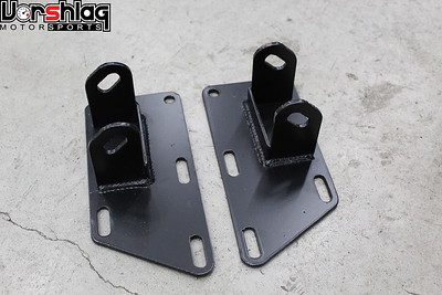 
The block side plates are pretty basic but we made them work. The mock-up GEN III LS engine we had on hand was fitted with G8 / CTS-V accessories, minus the power steering pump. We were still unsure if we'd convert this car to electric steering at this point (we decided against that later - other things started to "scope creep" so we pulled this back).
 
This isn't our first LS swap and we had engine swap long tube headers on hand from 5 different kits we sell, plus a few others, to test in the '67. We had several oil pans, including this one from "Summit" that has a kick out sump, trap doors, etc. We have used this pan on two other LS swap builds lately and it should work well for road course use with an LS, along with an Accusump. We tried a mid-length header first, and it didn't fit either side.
 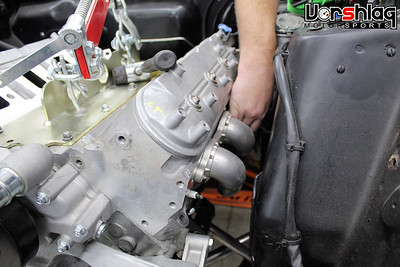
Then we tried this 1-7/8" long tube design from another swap, and it just fell right in. My wife Amy put in the passenger side and Evan the driver's side. These long tubes fit extremely well, as did the transmission, so we stopped to lock down the AJE crossmember location. I was pretty dang happy at this point - no new custom header design would be needed! FOR THE FIRST TIME EVER we already had an LS swap long tube header that could work on a completely different chassis. This never happens.
FINAL MOUNT AJE CROSSMEMBER
After the subframe was mocked up, and after positive testing and measurements with the LS engine and trans in the position set by the AJE mounts, we had a plan in place. We had test fit three LS oil pans, several intake manifolds, and fitted one of our long tube LS swap headers. The transmission we were using fit the factory shifter hole pretty well, too.
 
We had already adjusted the engine up and down, moved it front to back, and the only thing it did was add a lot of work - virtually no benefits. The Holley Hi Ram intake (below left) was never going to fit no matter the placement, so that tall intake was axed. And honestly it would be massive overkill for the modest 450-500 whp goal the customer had in mind. For a 2600 pound car that is going to be PLENTY of power - I suspect close to double what it came in here with.
 
So we left the mounts that AJE added to the subframe alone, had our front axle centerline set, and even some progress on the control arms for our custom S197 front strut / spindle / brake setup. It was time to lock down the subframe position and bolt it to the frame.
 
The K-member had been clamped in place for the previous tests and we had several inches of fore-aft adjustment room, but we locked it down in the position recommended by AJE. Evan marked the holes (above left) then dropped the K-member and drilled through the frame. The AJE kit comes with crush sleeves which were added and TIG welded into the frame holes (above right).
 
The holes / sleeves were fully welded and then sprayed with self etching primer, then the K-member was finally bolted in place. The mock up LS engine, the Summit oil pan, our long tube 1-7/8" stainless headers, and the transmission were reinstalled March 5th, 2020, right as we started to scale down hours in the shop during the lock down.

Again, apologies for the redacted images I have to use here. Getting the K-member in and the drive train installed was a good step - now we started talking about an affordable stroker 383" LS for this car, which we were putting together at HorsePower Research. We had two other track cars getting similar engines and felt it would fit the power goals, track reliability, and budget allocated to this part of the project.
CONTROL ARMS AND TRANS CROSSMEMBER BUILT
It was difficult to show the work to our customer but these images worked, and in person he could see that the transmission was appropriate for this tunnel size, the power output goals, RPM range, and both street and road course use. Again, will talk more about this when the NDA is lifted.
 
The crossmember is pretty basic, with a short span to support. We utilized a captured polyurethane Energy Suspension bushing which we have used on many LS swaps. The parts were designed in SolidWorks and cut on our CNC plasma table, as were the control arms shown below.
continued below

|
05-28-2020, 01:56 PM
|
|
Senior Member
|
|
Join Date: Mar 2014
Location: Plano, TX
Posts: 160
Thanks: 6
Thanked 67 Times in 33 Posts
|
|
continued from above
 
Myles and Jason worked on the control arm design based off the S197 Mustang design (2005-2014), using an S197 spindle/hub we keep on hand for design and testing purposes. Once the geometry was dialed in on the wheel testing task above, Myles ran some calculations using the OEM S197 front LCA. We bought the later S197 spindles (which upgraded from an 18mm to 19mm ball joint shaft) and Howe ball joints and threaded collars.
 
These ball joints are replaceable and the threaded Howe collars are more easily incorporated with a custom LCA design, and were used on the mock-up single plate designs to test geometry (above left). We talked about a tubular version but felt that a boxed, plate steel design would be more robust and accurately repeatable for the mirrored side-to-side design.
 
This later version had some round windows that we would later fill in with tubing to make the boxed structure stronger. Myles poured some hours into this design and the fabrication work.
 
We don't do "weld pr0n" around here, because most of that Instagram welding isn't practical, and it isn't always the right way to do ti. You can look at all of our builds and won't see any pics of "stacking dimes" - because that is better left to ego posting. Proper cleaning, the right rod, adequate shield gas flow, accurate heat, and the right penetration are what we shoot for here.
 
Above left you can see the tubing sections being added to the holes, for strength. Lots of tedious work went into these boxed Lower Control Arms. The control arm mounts were tubular sleeves made to fit within the AJE subframe, and to work with Whiteline bushings we ordered to fit the OD and ID needed.
 
Having the sleeved mounts aligned was critical, so a couple of welding fixtures were machined to fit the ID of the tubing as well as set the spacing to mach the crossmember. We will keep these on hand, along with our CAD designs, in case we ever have a need to make these LCAs again.
 
The rounded ends at the ball joint mount were "boxed" in with a final piece of steel. All of the parts were CNC cut but that doesn't make the welding and prep work any easier. After both arms were fully welded the Howe ball joints with S197 stubs were fitted with the rubber boots. No distortion and they threaded right in.
 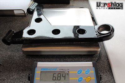
This might seem like an excess number of pictures for Lower Control Arms, but these are critical to this entire build and we built them in a new way - for us. They came out very strong, rigid, and relatively light weight. They will allow us to use a modern S197 spindle / hub / brake / ABS with a cost effective tubular crossmember from AJE - that had LS motor mounts built in.
 
I took the LCAs and trans crossmember to have them powder coated, which wrapped up that portion of the fab work. This brought the build into early April 2020, and I will show more of these parts in a future post.
continued below
|
05-28-2020, 01:57 PM
|
|
Senior Member
|
|
Join Date: Mar 2014
Location: Plano, TX
Posts: 160
Thanks: 6
Thanked 67 Times in 33 Posts
|
|
continued from above
COMPOSITE DOORS
The dreaded Scope Creep started to happen here. When this '67 Mustang project came in it was still a "street car that could occasionally do track events". It had a 4-point roll bar, full interior, and working air con. As the project progressed the owner quickly re-focused his already listed safety goals to match the increased performance we were adding. To mate the power output of the LS7 the safety goals went up to match. Instead of a reconfigured 4-point roll bar it was time for a proper roll cage, and by then the car became a dedicated track car "that can be driven on the street".
 
After the cage had begun we talked about door bar options - a simple "X" that allows for an interior door panel, or a more roomy NASCAR style door bar, as shown above. After seeing the difference in person, and noting the lateral room gained when we push the bars out to the outer skin of the door, Adam wanted to go ahead and use NASCAR style door bars. That means ditching the door panels, the door windows, and the interior.
 
We asked him several times if he was SURE that's what he wanted - because going this route shrinks the number of people willing to buy any car when it is completed. Caged race cars are harder to sell than street cars with some tasteful mods. But as you can see by the other mods that have been added as we went along, this has turned into a more serious track build. And the door bars will add a lot of side impact protection and extra room for both the driver and passenger.
 
Adding safety usually means adding WEIGHT - which is always the enemy of speed. The OEM steel doors are always heavy when chock full of crash beams, window mechanisms, glass, and speakers. These were no different at 76.0 pounds each. So when he asked for NASCAR door bars, the need for OEM door impact protection went away - so I suggested these cost effective composite doors from VFN.
 
These fiberglass doors were purchased and weighed in at a paltry 14.5 pounds - and that's before we clearance them for the cage's door bars. This weight savings will be about a 123 pound drop, which should offset the weight gain of the full cage over the 4-point (and then some).
 
We have used VFN body parts before and they fall in at the more affordable end of the spectrum of quality, lightweight composites. Way better than cheap import stuff, but not quite Motorsports Dry Carbon level. Evan checked then marked the mounting holes (dimpled in the mold) and drilled them for the door hinges. We will use the OEM hinges without the return springs. Evan made some templates from these hinge mount holes, then Myles CNC cut some backing steel plates for "doublers" that go on the inside of the door structure.
 
Evan then tack welded nuts to these plates, which are riveted to the door structure. Makes installation and removal a breeze and strengthens the part of the door that sees the highest loads - the hinge points.
 
A little time was spent "fitting" the doors, but with aftermarket composite front fenders and composite doors from another company, they don't "play nice together". As is the case with some composite parts, both the Maier Racing composite fenders and VFN doors are made a little "long" so you can trim them to fit. We are not a body shop, so I will deliver the chassis to our painter (as soon as the suspension is done enough to let it roll into my trailer) and have him adjust all of the panels on the front of the car, from the doors forward.

The body shop can trim the doors and fenders to have a better fit so we can open/close the doors. Until then we will either have the doors -or- the front fenders on, depending on what we are doing. You won't see them both installed from here until they are properly fitted.
continued below
|
|
The Following User Says Thank You to Fair For This Useful Post:
|
|
05-28-2020, 01:57 PM
|
|
Senior Member
|
|
Join Date: Mar 2014
Location: Plano, TX
Posts: 160
Thanks: 6
Thanked 67 Times in 33 Posts
|
|
continued from below
LS7 CRATE ENGINE + TRANS INSTALLED
As we were wrapping up one of the first in a series of "affordable" LS road race engines at HPR, we had a good grasp on the price and output numbers. This was to be a cathedral port, aluminum block, 383" LS stroker, wet sump road race engine - I gave the pricing to give Adam. I had one of these being built for my LS550 project and we could see a 450-550 whp power range depending on the cam, intake, and some other aspects.
 
This would take more than 2 months to build, due to the backlog of engines in process at HPR, plus some added delays due to Covid-19. This 383" long block would still need: intake manifold, fuel rail, injectors, throttle body, ignition coils, the Summit road race oil pan we talked about, water pump, pulley, flywheel and clutch - but it was still a very good package price. It was until he went and found these GM crate LS7 dry sump 525 hp 2015 Z/28 spec engines on "Coronavirus Sale" at $10,900...?! I researched this deal, which seemed unbelievable, but it was true.
 
I couldn't get the HPR 383 LS6 down to that price level after I added in all of the extras that the crate engines come with, not to mention this has the LS7 dry sump oil pan, extended snout crank, and 2 stage oil pump. Just the bare LS7 block alone costs $3800 - GM must have needed some quick cash to slash these LS7s down to this price! These are the later 2015 spec so they have improved titanium rods, better valves, a bigger oil pan, and several other updates. We're not going to touch the engines internals or cam, and will even use the included flywheel and clutch. Saves time and money and adds displacement. And he can just tell the Ford Faithful it is a 427" V8... they can think its an "FE" series Ford Big block if they want, as long as he doesn't open the hood.
 
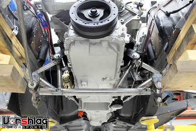
Of course getting a complete, dressed crate engine will save time on this build. After we unloaded the engine from the crate, Evan stripped off the intake and coils, so we don't damage them when installing the engine into the car. Brad and Evan put the long block and bellhousing in without drama using our engine tilter and engine hoist.
 
I was a little worried that the 2015 Z/28 oil pan might have some clearance issues but that was not the case - fit by a large margin. These LS7 dry sump engines still have a lower oil sump, so we can't lower this any more than we could our mock-up engine. Evan reinstalled the intake and coils with the engine back in the car for the last time before it fires up.
 
After testing the TOB engagement & input shaft depth, the transmission was fitted, as were the hydraulic Throw Out Bearing slave line and remote bleeder, with a quick connect on the pressure line. Had the pressure line made to fit the hydraulic clutch master cylinder Adam had installed for his T5 before. We then installed a new starter. This thing is ready to plumb, wire and fire!
 
We still have work to do - with the engine and aluminum radiator in place we can route things like the Cold Air Intake, pick a filter, and find a place for the dry sump settling tank. We have discussed the EFI system and digital dash options with the customer and that is on order, so it could be running in a matter of weeks.
WHAT'S NEXT?
I had a whole section on the fuel cell, but I will show that next time. It is a beautiful piece of engineering, with an internal surge tank. That was all assembled and mounted last week.
 
We also have the 18x11" Forgestar F14 Super Deep wheels on hand already. A bunch of new parts have arrived for the front suspension: S197 spindles, front hubs with ARP studs, the custom control arms we built, the 14" diameter 4 piston Brembo brakes, and the MCS TT2 doubles arrive later today. The custom camber plate & welded on strut top design are wrapping up as well.
 
This week we have made some good progress on the cage, and we were test fitting seats with Myles (5'11") showing how much head room we gained to the upper door bars with the lower seat mounting. This post is already running long so I'm going to call that good until next time - should have another tech filled post showing more progress on this car soon.
Thanks for reading,
__________________
Terry Fair @ Vorshlag Motorsports
|
|
The Following 6 Users Say Thank You to Fair For This Useful Post:
|
|
05-28-2020, 04:29 PM
|
|
Senior Member
|
|
Join Date: Apr 2014
Location: ATL
Posts: 748
Thanks: 11
Thanked 58 Times in 36 Posts
|
|
Thanks for the Mustang update, Terry! I read a lot today, because somebody paid me to do so, but your post was by far the best content.
It's great to see both the cost consciousness and the attention to what is most likely to work well (via experienced perspective) in the same space. Usually, I will laugh if someone decides that a full-price LS7 is the "answer," but in this case, the discount probably definitely made it worthwhile. Realistically, a 6.0 truck motor will make LS7 power pretty easily N/A, but sometimes one just must have Ti parts inside the aluminum block . . .
The creativity that comes through in these builds is much appreciated.
|
|
The Following 2 Users Say Thank You to rustomatic For This Useful Post:
|
|
05-28-2020, 05:39 PM
|
|
Senior Member
|
|
Join Date: Feb 2005
Location: Dallas TX
Posts: 694
Thanks: 78
Thanked 230 Times in 157 Posts
|
|
Quote:
Originally Posted by rustomatic

Thanks for the Mustang update, Terry! I read a lot today, because somebody paid me to do so, but your post was by far the best content.
It's great to see both the cost consciousness and the attention to what is most likely to work well (via experienced perspective) in the same space. Usually, I will laugh if someone decides that a full-price LS7 is the "answer," but in this case, the discount probably definitely made it worthwhile. Realistically, a 6.0 truck motor will make LS7 power pretty easily N/A, but sometimes one just must have Ti parts inside the aluminum block . . .
The creativity that comes through in these builds is much appreciated.
|
x2. Lots of info & explanation behind the 'whys'.
|
|
The Following 2 Users Say Thank You to ScotI For This Useful Post:
|
|
05-28-2020, 08:35 PM
|
|
Lateral-g Supporting Member
|
|
Join Date: Nov 2008
Location: Dunwoody, GA
Posts: 6,537
Thanks: 1,326
Thanked 802 Times in 609 Posts
|
|
Thanks Terry! Love reading your updates. I'm happy this project is still on track.
For me, stock LS7 engines are amazing. They make so much power everywhere and are so docile. That's a hell of a good deal you guys found.
You guys making 315s fit all four corners really puts a damper on my getting excited for 275s on all four corners of my car, lol. This thing will look like a roller skate once it's on its wheels
__________________
Trey
Current rides: 2000 BMW 540i/6 and 86 C10.
Former ride: 1979 Trans Am WS6: LT1/T56, Kore 3 C5/6 brakes, BMW 18in rims
|
|
The Following 2 Users Say Thank You to WSSix For This Useful Post:
|
|
02-02-2021, 08:51 AM
|
|
Senior Member
|
|
Join Date: Mar 2014
Location: Plano, TX
Posts: 160
Thanks: 6
Thanked 67 Times in 33 Posts
|
|
Project Update for January 30th, 2021: Since our last post in this thread in May of 2020 we have finished a huge chunk of work to this Mustang. After we got to a point where we needed fenders and hood to fit things, we loaded up the car and I trailered it to the painter to have bodywork fitted (October 2020), and while there, things snowballed into a lot of body work - but with amazing results. The car came back from the painter on Christmas Eve 2020, looking very complete and ready for paint.
 
From May to September we completed a ton of tasks: strut towers were modified and reinforced, initial camber plates built, spindles and brakes installed, steering completed, and the front suspension was wrapped up. A power steering pump was modified and installed, a bit of cage work completed, the 18x11" wheels and 315mm tires were fitted, a fuel cell was ordered and mounted, the entire fuel system was plumbed, and the Holley EFI system was wired. Long tube headers fitted, cooling system started, and hood hinges modified. Tremec has since released their TKX, so I can show that now. At the body shop a new hood was installed, the front doors and fenders were fitted, the rear wheels flared, a carbon lower air dam went on, and the whole body was blocked, sanded, adjusted, sanded some more, and primed.

This Mustang is coming along nicely, as you can see in the image at the body shop, above. We have had some personnel changes in the months form May to December, and have found a great fabricator in Zach, who will wrap up a lot of the remaining work in 2021. Brad spent some months finishing up our shop construction, and we now have a more efficient area to resume work. Lots to cover on this projects so let's get started!
FRONT SUSPENSION WORK
Myles and Jason had been working on the front suspension for quite some time, and the front control arms were designed around the stock shock tower placement (which would be heavily modified) and a 2011-14 Mustang GT "S197" spindle, hub and brake.
 
Evan took the the templates and we scanned those in to make some CNC cut plates that fit inside the towers and key off of certain stock locations. The goal is to make something we can reproduce in the future - which could be installed by others in their own home garage. We tooled up a temporary camber plate and strut to get some dimensions, then Jason drew up custom front struts which we had built by Motion Control Suspension (MCS) out of Georgia.

These double adjustable, S197 style MCS front struts arrived May 29th, 2020. Things started to happen more quickly after that point.
 
With the temporary strut tower and camber plate installed, brand new 14" rotors, 4 piston Brembo calipers, ARP stud equipped S197 hubs and new S197 spindle were installed along with our custom lower control arms in the AJE cradle. Evan mocked up one of my 18x11" wheels and 315/30/18 Hoosier R7s on the front and we started some geometry checks.
 
Juggling with wheel spacers we took these S550 fitment front wheels and were able to tuck them within 5mm of the strut, which we do to maximize front wheel room. Steering angle looked excellent - lots of room and lots of total steering lock possible. Time to lower things down and get the car off the front dolly that it had been bolted to for many months.
 
Seeing this really got everyone fired up. The big 11" wide wheel, 315mm Hoosier, the Brembo calipers and meaty rotor in there... wow. With the front fender installed we realized we had plenty of room - these massive wheels might have fit with the stock fenders, but they were long gone. Time to get to work on the final strut tower design with the suspension in place, and initial camber numbers in hand.
 
The initial setup had too much negative camber so the strut tower was built to take away some of that, but still give plenty of adjustment range. We also designed this to give ample positive caster adjustment.
 
As the strut towers were reconfigured to take full suspension loads and not just shock loads, the steel plates we CNC cut were welded in and massively reinforced the whole area. A well anchored strut tower brace will also be designed and added. A temporary CNC plasma cut camber plate was cut and installed, but the final version will be CNC machined from aluminum and use counter sunk (flush) bolts for the caster adjustment.

By the end of June we had strut towers modified, the MCS struts / brakes / hubs installed, and both of my 18x11" MOMO Heritage 6 wheels and 315mm Hoosiers installed. The car was on the ground and rolling again - the dolly that had been holding up the front end for months was taken apart and put away.
FENDER ISSUES + FORGESTAR 18x11" WHEELS
We had great luck fitting the VFN fiberglass doors, as we know this brand and have used it well on other cars. But the Maier fenders really fit very poorly, and the side-to-side differences were quite astonishing. The fender openings were off by 3/4" side to side! We cannot install either fender with the doors installed, because they are made much longer than the stock fenders. We had marked center on both sides and "split the difference" for our front axle centerline.
 
Making these fenders fit with a Maier supplied hood would end up taking nearly 2 weeks at the body shop, who had nothing good to say about the quality of fit of these parts. They had to modify the arches to sort of line up side to side and shorten the rear lengths to fit the doors.

To get the fender tops and hood to line up took DAYS of work and a LOT of fiberglass filler - and these are parts from the same company. Lots of time was spent sanding, fitting, and blocking to get the body lines to look like this. Many thousands of dollars in bodywork to get this level of fit. Just be warned - not all aftermarket composite bodywork is made the same. Don't let a "name" fool you into thinking these parts actually fit well. They don't, not without a LOT of work.

Adam's Mustang rolled in here on some Shelby replica wheels in 17x8" front and 17x9" rear with 245mm Michelins. The tires were flat spotted badly in the front, due to some brake components made by Wilwood that had what appears to be horrible front to rear balance. We're fixing that with modern Brembo brakes and ABS, but the little bitty wheel and tire package is getting a major re-do also. This 18x11" Forgestar F14 Super Deep wheel set was ordered for another car in the shop and it just so happened to be a near perfect fit for Adam's Mustang.
 
This happened at the perfect time for Adam - a set of wheels that fit his car arrived in the right size, without the 4+ month wait we usually have to sit thru for their wheels. All it took was some longer wheel studs in the rear and a bit of a spacer out back. These 3" ARP studs went in place of the short 1-1/2" studs in the Currie axles out back.
 
Brad and Evan dialed in the spacer thickness needed until I liked the inboard wheel room to the chassis, above. We can get away with 1/2" of room there due to the Watts Link and 3-link rear suspension under the car.
 
Brad noted that the axle was not centered, so he checked and adjusted the axle to have the same side to side measurement. Then a set of 315/30/18 Rival-S 1.5 tires were fitted to the wheels and they looked great on the car. The outer fender lips would need a little massaging, but no "mega flare" work would be needed.

The fronts bolted on with no spacer and no tricks. These were the perfect offset, astonishing. Sometimes you get lucky. The spacer setup on the rear is very minor and will allow Adam to rotate the same wheels front to back, for an ideal track setup. The deep spoke offsets look REALLY good on this little coupe, too! So by the first week of July 2020 we had the final wheels and tires on the car, which was a big step.
FUEL TANK REPLACEMENT & TRUNK WORK
 
Evan removed the fuel tank in early May to do some rust repair in the trunk. Just a small section at the right side, but too close to the tank to do without removal. We also were looking at a solution to properly feed a dry sump 427" LS7 on track with big fat 315mm tires we would soon install.
 
Evan got the rot repair done, quickly and beautifully. Now it was time to talk about options. After researching a few replacement fuel tanks, looking at remote surge tanks, and offering up a fuel cell option - Adam went with this modular 15 gallon Radium Engineering fuel cell with integrated surge tank, pumps, and FIA certs.
 
This was a relatively new offering from Radium Engineering, available piece by piece or as a complete fuel cell, with lots of options.

This is the real deal, and comes in 5, 10, and 15 gallon versions. I only wish they made a 20 gallon, then we'd have them in several road race cars. This is a full containment can, Kevlar bladder, foam, the works. We ordered this 15 gallon version with the "FCST" upper, fuel level pickup, filler neck and cap, and supplied our own pumps.
 
The best part of this complete fuel cell system is the integral "Fuel Cell Surge Tank" portion of the tank. These integral surge tank tops can be ordered separately for other fuel cells, and they make variable depth pickups and fuel level sensors. Evan lobbied hard for this, as he has one in his own race car. This is a thing of beauty and precludes the need for an external surge tank.
 
All of the wiring connections are on the top, as are the filler neck, rollover valve, and feed/return lines. Evan added Walbro 430 pumps for the lift pump (at right, with the sock) and the internal surge tank (which can take 1, 2, or 3 pumps). Then the internal surge can (black part shown below left) was added and it was bolted into the Radium cell.
 
All of the internal wiring is connected and ready for plumbing at this point - it went together quickly. You can even order this with pumps and then they pre-assemble the whole thing. Very slick system.
continued below
Last edited by Fair; 02-02-2021 at 08:58 AM.
|
|
The Following User Says Thank You to Fair For This Useful Post:
|
|
02-02-2021, 08:56 AM
|
|
Senior Member
|
|
Join Date: Mar 2014
Location: Plano, TX
Posts: 160
Thanks: 6
Thanked 67 Times in 33 Posts
|
|
continued from above
 
We ordered this with the optional mounting cage from Radium. Sure, we could have built this, but not likely for as little as they charge. The work now was making this fit the larger opening of the stock tank. We experimented with front to back as well as height adjustment then Evan started making the pieces to fit that spot.
 
With some steel angle tack welded in place and load spreader plates at the rear frame rails, the mounting cage was clamped in place. Then some a drill fixture was made from CNC machined bushings we use for something else.
 
That allowed him to perfectly drill these smaller holes though the Radium cage and into his angle structure. The angle structure was then finish welded and primed in the car.
 
The final install of the cage (above left) uses hardware from the steel can of the fuel cell (above right) and bolts into threaded inserts through the cage and into the steel angle mounting structure Evan added.

This ended up being one of the slickest - and quickest - fuel cell installs we have ever done. This won't be the last Radium Engineering modular fuel cells we install, that's for sure.
DRIVETRAIN REVEAL
Some of this has been known before - this car came in here with a built Currie Ford 9" rear axle (below left) and we added the crate 525hp LS7 (below right).
One thing I was under NDA not to disclose until November 2020 was the Tremec TKX 5 speed manual transmission, which we got early due to our testing relationship with Tremec.
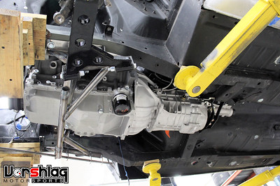 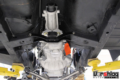
This is a clean slate redesign of the old TKO transmission with modern 3-piece synchros, carbon blocker rings, a new case, new everything. It is still very compact and lighter than any T56 Magnum, which would have taken tunnel surgery work to make fit. As it is the TKX was a super easy install. We did zero cutting, just made the transmission crossmember shown. That's it. It bolts right in.
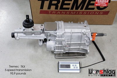 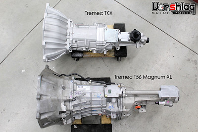
The T56 Magnum was what we would have used, but when the opportunity came up to test the TKX on two chassis in our shop (E46 LS swap endurance car + this 67 Mustang) we jumped at the chance. The TKX seems perfect for this build, as it is lighter (95.9 lbs vs 128 pounds for Magnum XL) and smaller than the Magnums in every dimension.
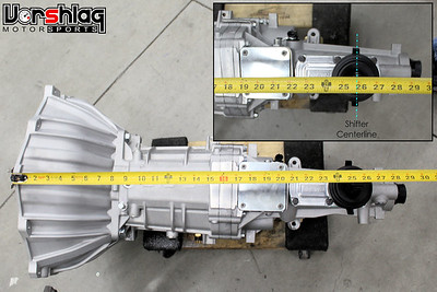 
The TKX is a great size for this car, and I took a measurement showing the bellhousing to rear most shifter location above. It is rated for 600 ft-lbs of torque and comes in several gearing options. We had this bolted up to his crate LS7 engine in early May 2020.
 
The RAM heavy duty hydraulic throw out bearing slave kit was used, shown above left. This slides over the input shaft and one bolt on the front bearing retainer is replaced with a stud to locate the slave. This was shimmed to work with the LS7 clutch and flywheel that came with the crate engine.
 
We built custom lines for the Wilwood slave cylinder that Adam already had in the car for use with the T5 the car used to have. The crate motor came pretty complete but Evan removed the intake and exhaust manifolds to make installation easier.

With the appropriate bellhousing attached the engine was attached to our hoist and leveler and Brad and Evan installed this into the chassis in early May 2020. We had a mock-up LS engine in place for months while we worked on the TKX crossmember and other work.

The stock Tri-Y manifolds were too bulky to fit but these 1-7/8" stainless long tube headers we developed for another LS swap happened to fit perfectly. After 12 different chassis we have swapped so far, we FINALLY got lucky and had one set of headers that actually fit. This saved us MONTHS of development work. I will show the header install in another section, below.
ROLL CAGE WORK
In late May we made some good progress on the roll cage. We had already cut out the old 4-point roll bar, relocated the main hoop back almost 10 inches and added some "feet" to mount that onto the rear seat shelf. This gives more room to the driver and we were able to raise up the hoop to nearly touch the roof skin.

The rear downbars were re-routed to the trunk and then Evan started on the forward hoops along the top of the doors and down the A-pillars.
 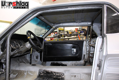
That worked out well, and we will not add a "dash bar" - which would require a lot more surgery. Instead the factory dash will remain intact. This car is being built for fun HPDE and Time Trial events, not wheel to wheel racing. It will also be street driven, so some compromises are being made to accommodate both track and street use.
 
At the end of May, Adam came by and we test fit him in the car (above left) with multiple seats, including this Sparco EVO II and his Corbeau seats the car came in with. This helped us design the floor mounting brackets, which will also reinforce the somewhat weak factory floor.
 
The shop schedule got pretty hectic but at the end of July, in his last weeks with us full time, Evan managed to wrap up the upper windshield bar. This was bent, fitted, and tacked in place.
 
He also finished the main hoop diagonal (above left), which was fitted around Adam's seating position. The rear down bars were also tacked in place with load spreader plates in the trunk. The only tubes left are the harness bar and door bars, which will be "NASCAR" style and cut into the composite doors. The cage is only tacked in place, and the front tubes land on removable plinth boxes. When the door bars are complete we will drop the cage down off the plinths, finish TIG weld the tops of the cage, then raise it back up and finish the rest of the welding in situ.
COOLING & OILING SYSTEM PARTS ADDED
Back in July, as the he LS7 and TKX drivetrain were installed, it was time to start looking at the cooling and oiling system parts needed. Adam had a nice oversized aluminum radiator and large electric fan, so those were reinstalled and will be utilized - with some additional shrouding panels ahead of the radiator.
 
It was time to lay out where the coolant reservoir and oil tank would fit. We ordered this billet remote coolant reservoir from Radium and it can fit lots of places, since the size is pretty compact. But not there, above right. Something else needs to go there.
 
The oil settling tank needed for the LS7 dry sump system is rather large, but the OEM version is one of the only ones out there that has an actual dip stick. It seems crazy, but its true - so we ordered one of these from a local race shop. Measuring proper oil level in aftermarket dry sump tanks is amazingly difficult. I asked Evan make a cardboard cylinder to mimic the OEM tank's shape and it looked like nowhere would be good fit, without some cutting.
 
We determined that the only viable spot for this tall oil tank was the RF corner of the engine bay, and Evan cut away some of the inner fender to make room. It was at this point that we realized that we needed the fenders, hood, and headlight buckets installed to lock down the final location - as the tank was going to need every inch of room vertically, and would be close to the headlights and tires.
 
This is where we stopped on these systems in July 2020. We needed to finish the fuel system to finalize layout of the regulator and cold air inlet tube, and we needed the nose back on the car to layout the engine oil and power steering coolers. We knew roughly where they could fit but didn't want to order those pieces until we were sure and had the body all put together.
POWER STEERING PUMP
Adam had issues with the power steering pump with the old 1985-90 5.0L Ford V8, and had purchased an expensive KRC road race style power steering pump kit to fix that issue with on the old V8.
 
When it was determined that he wanted to stick with hydraulic power steering on the LS7 engine, we called up and ordered the LS7 bracket and proper pulley (above right) for use with the LS brackets and RPM range the engine could see.
 
These parts arrived after Evan had left us, but he came back for a few days in September and knocked out the pulley swap, which is not a trivial task unless you have the right puller and installation tools. The bracket bolted to the block, as shown above.
continued below
|
|
The Following User Says Thank You to Fair For This Useful Post:
|
|
 Posting Rules
|
You may not post new threads
You may not post replies
You may not post attachments
You may not edit your posts
HTML code is Off
|
|
|
All times are GMT -5. The time now is 05:59 PM.
|


 Brian Hobaugh SCCA National Tour June 2014
 First Hemi 'Cuda Convertible Ever Built
 Short clips: Goodguys Pleasanton autocross and pit videos


 Hybrid Mode