continued from above

So Ryan began designing a custom, complicated assembly of brackets on the driver's side of the block to mount the power steering pump, the new small alternator, and an idler pulley.

He made templates from cardboard, then more durable ones from MDF, which helped him perfect the patterns before going into CAD.

The power steering pump is at the bottom left of the engine bay....

...and the alternator is at the top on the same side. This was needed to clear the tubular structure of the front control arm mounts and narrower frame rails - which were needed to get the proper suspension geometry and camber settings for the existing wheels and tires the customer wanted to keep.

After the templates were perfected in CAD they were printed out in 1:1 scale, trans transferred to aluminum plate, and cut out on the vertical band saw.

There were several aluminum plates, machined spacers and various hardware used to tie it all together and mount everything to the block and cylinder heads.

This is what the assembly looked like off the car with the alternator and power steering pump attached (foreground) along with the cast bracket it was replacing (background). We didn't use computer simulations and FEA to remove every ounce from the bracket assembly, as some have asked about darned near everything we've done along the way. That just isn't practical for this type of one-off track car build. Sure, if this was a $500K, full-effort, pro race car, then maybe. Instead the assembly was built with rugged materials and hardware using experience and forethought, and it should make for a rigid set of mounts for these accessories.

This is what the bracket looked like attached to the motor, along with the idler at the bottom - as shown above. The brackets were all hand cut, edges were ground and sanded, and we will anodize these parts when the car comes apart for paint. Clear or black, maybe even a color? Its up to the customer and won't cost much. Leaving them raw is an option but they will get water spots and such that have to be scotch-brited out.

Here we have the brackets and accessories installed with the correct length serpentine belt installed (we tried a few sizes to find the best fit). There is "good wrap" on the crank pulley, alternator, both idlers, and the water pump and power steering pulleys.

It was a dozen hours of measuring, design, and fabrication work but this assembly is
critical to keeping the belt aligned (to avoid slinging the belts off at high RPMs) and to keep all of the accessories mounted firmly to the engine, nestled between the narrow frame rails. Losing a belt can lead to loss of electrical power, coolant flow, and if you are really unlucky, a flying serpentine belt can kick the cogged belt off the dry sump oil pump drive - and that can get costly in a hurry.
WHAT'S NEXT?
That was September's work, which wasn't exactly super sexy aero bits or big suspension work, but it was all necessary to move forward.
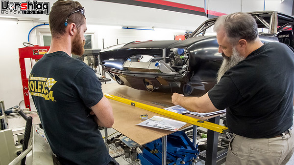
Next time we will finally cover the splitter + new lower valance design + the hood duct layouts. We sent a lot of images to the customer back and forth before we cut metal, and even sourced a flat hood to test hood ducts without the raised cowl hood restrictions.

Ryan was working on some other projects and on vacation for a week that month, so this was all of the September work completed on the 69 Camaro.
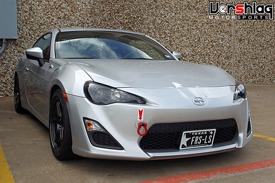

We also had the LS-FRS in the shop for a bit of follow up work, and took a bone stock 2003 NB Miata to a fully caged and prepped track car in 3 weeks, plus did more work on the LS Miata and other cars - all during September. It was a very busy month in the shop, for sure.
More next time,


 Brian Hobaugh SCCA National Tour June 2014
 First Hemi 'Cuda Convertible Ever Built
 Short clips: Goodguys Pleasanton autocross and pit videos


 Linear Mode

