Been quite a while since I've made an update to this thing. I cut the openings for the subframe connectors just before Thanksgiving and that's when things ground to a screeching halt. Thanksgiving, a ton of work before a Christmas shutdown, then two weeks of gift shopping, food shopping, cooking, cleaning, wrapping, visits hither and yon, house guests, a trip to Phoenix for New Years and then a ton of work to make up for no work over the last two weeks....cripes!
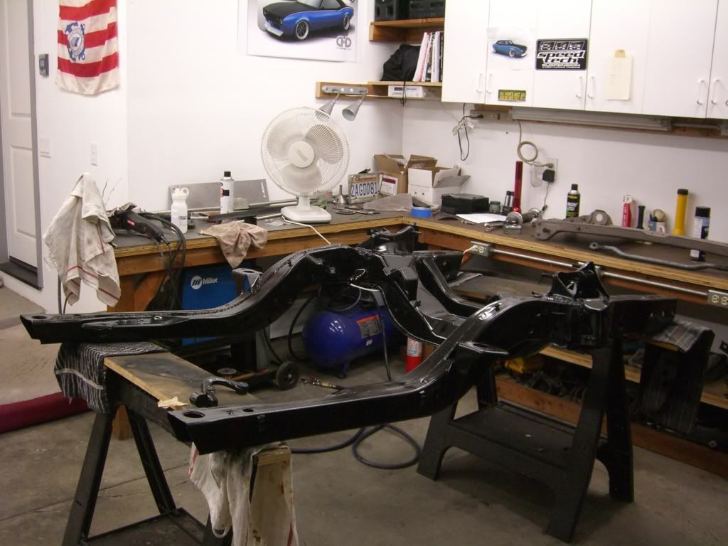
Well, I did eventually get a little time to finish the subframe connectors. Read on.......
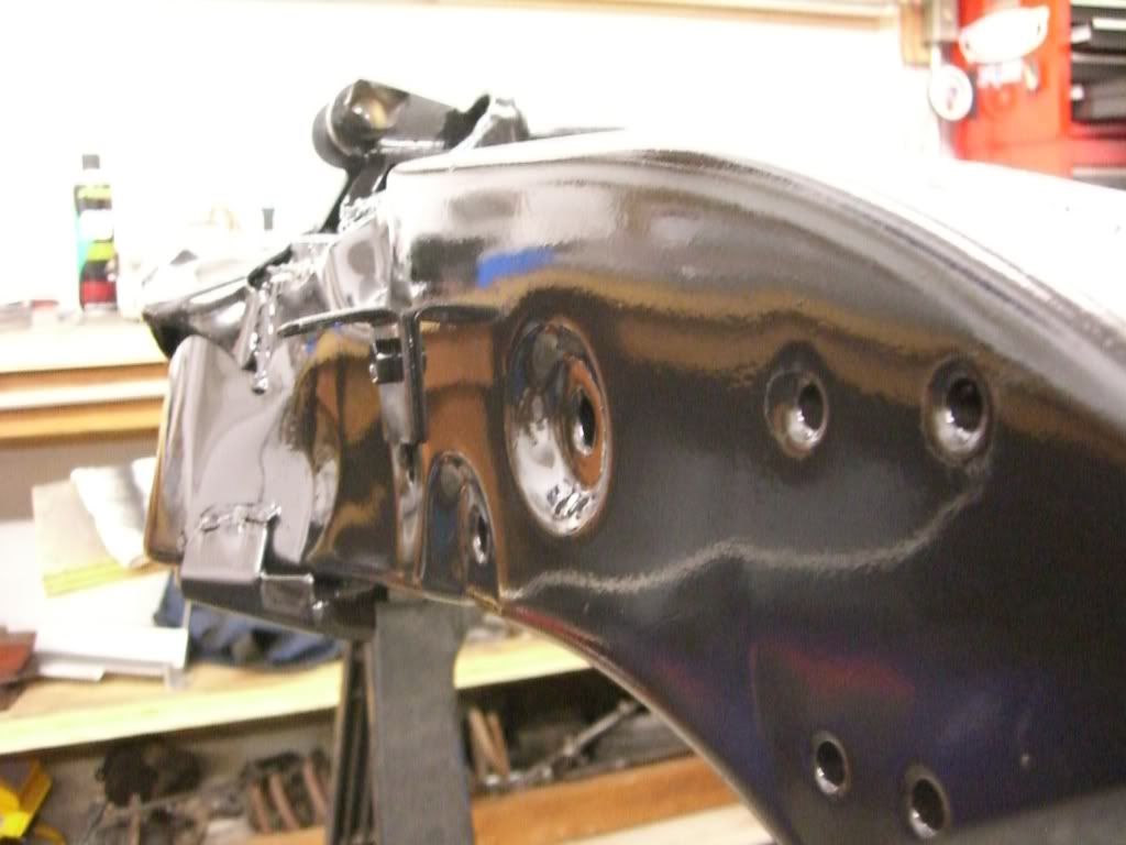
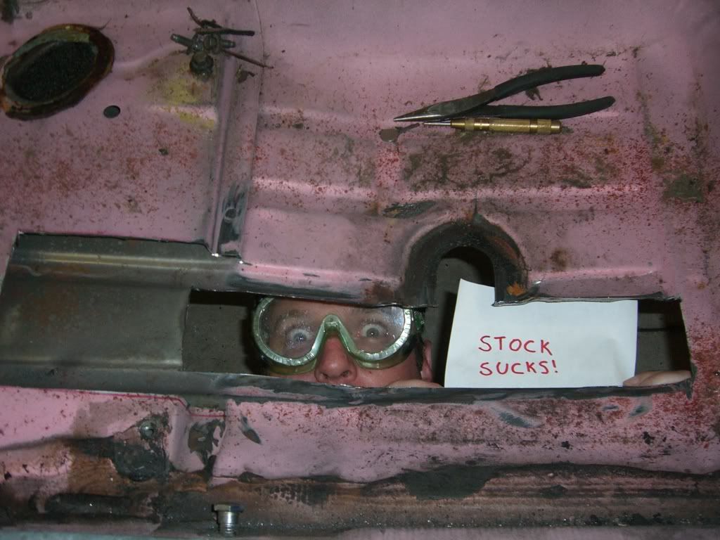
As I mentioned previously, it's a liberating experience to cut your first big hole in an old car!

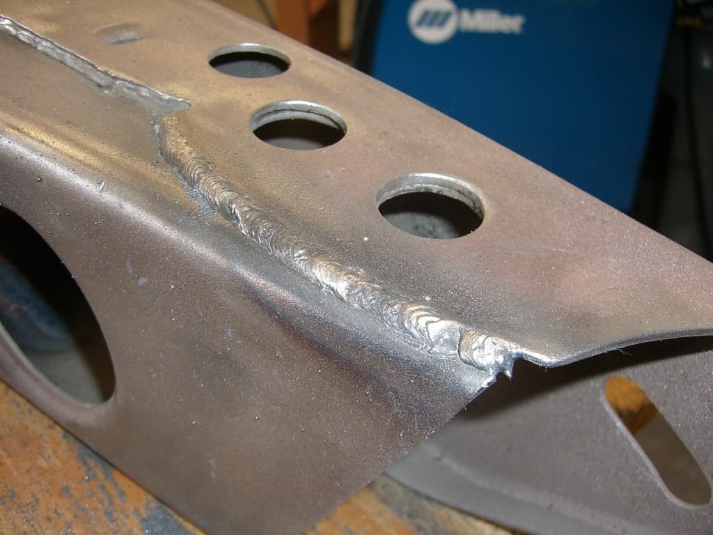
Cutting the holes was pretty straightforward. I used a cutoff wheel on a 4.5" angle grinder. It made pretty short work of it. I think a cutoff on a pneumatic would be easier, but since the compressor I bought is not up to the task it had to do.


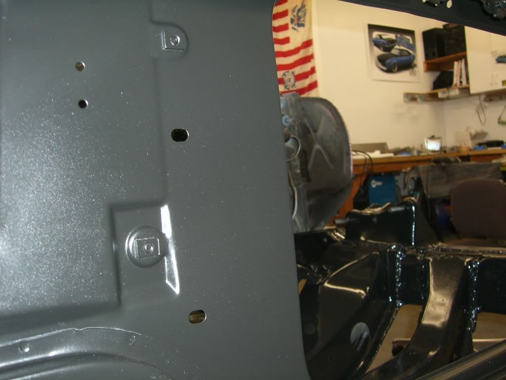
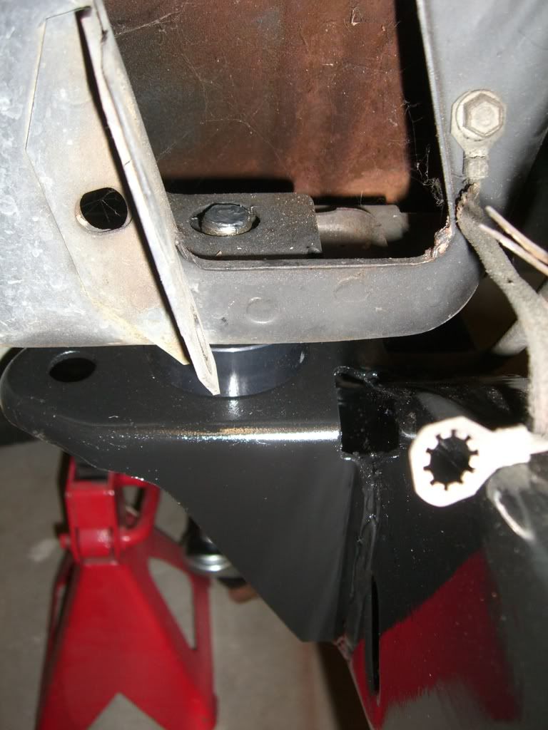
The only real concern here is to be very careful to cut the hole undersized and sneak up on the fitment of the connector. I used a grinder to whittle away at the material until the connector just fit. My welding is pretty bad so I wanted the gaps as tight as possible. Not too bad.

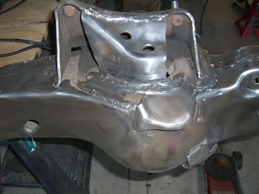
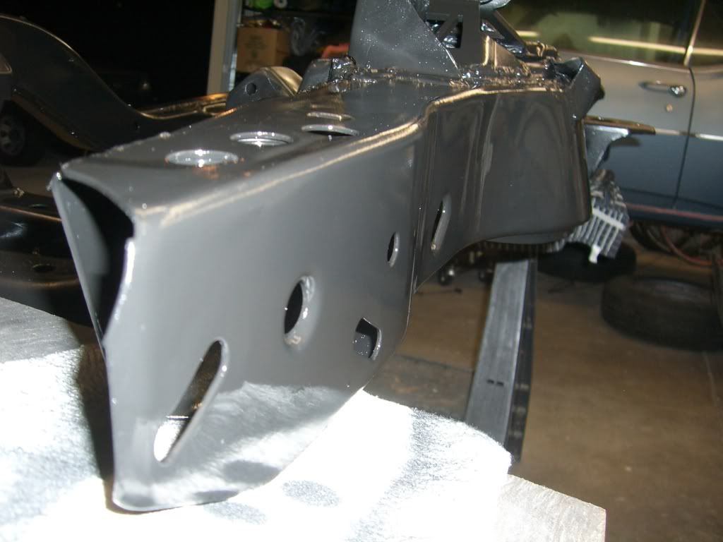
Then it was just a simple matter of welding it in (yeah, right!). Welding the seam on the inside of the car was pretty simple. Though 18ga to 3/16 steel requires a bit of fiddling with voltages and wire speeds. It wasn't awful though.


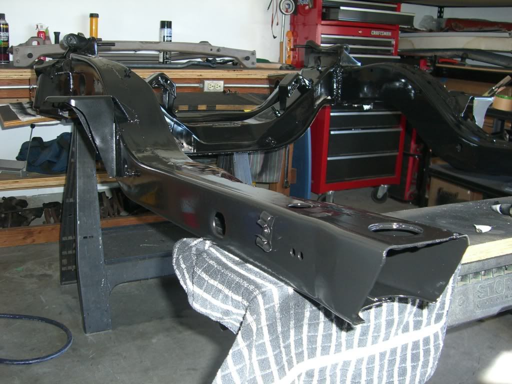
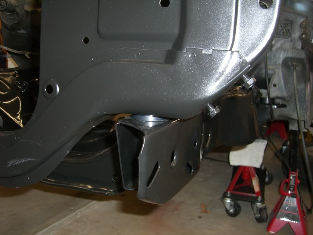
Where it got tough was underneath. The outboard bit wasn't too bad but the inboard side was a horror show. It's still technically a "T-joint" but the floor pan has those rolled beads in it and one of them directly abuts the subframe connector. So instead of a straight 90degree angle the joint looks like a lower case "h" and you are trying to do your welding up inside the bottom of that lower opening. Really tough work. I burned through the floorpan in a few places and had to patch it but eventually got it all done.

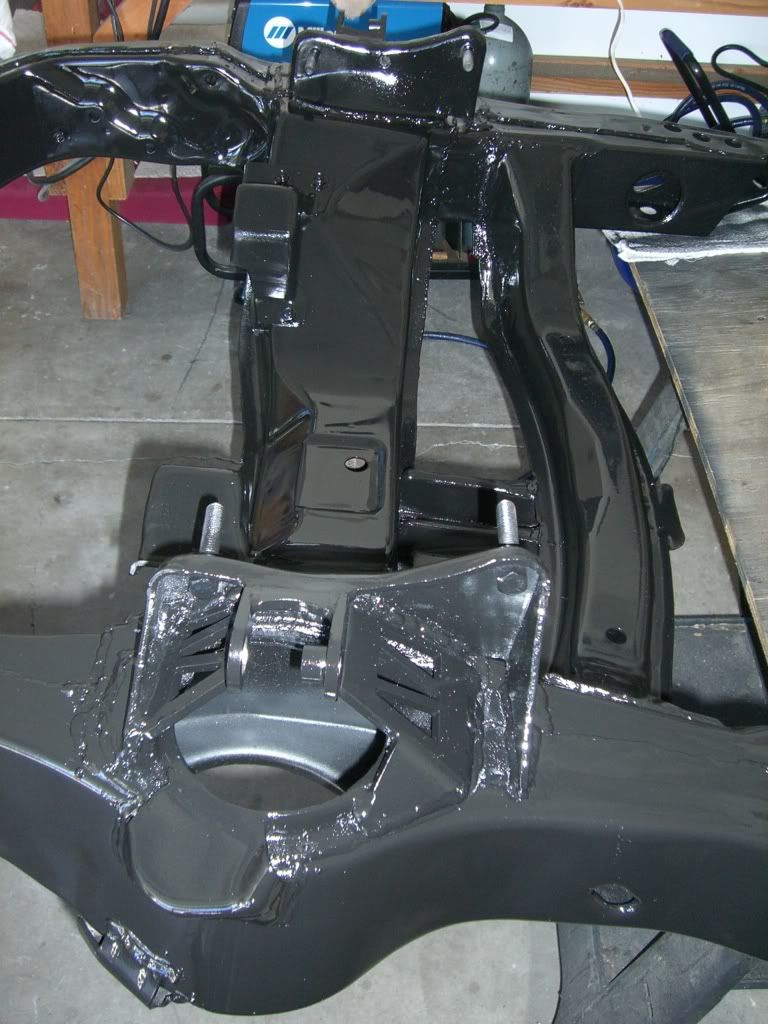
The fwd spring hanger blocks a bit of the joint between the connector and the rear frame rail so I'll have to zip a bit more of that together later.
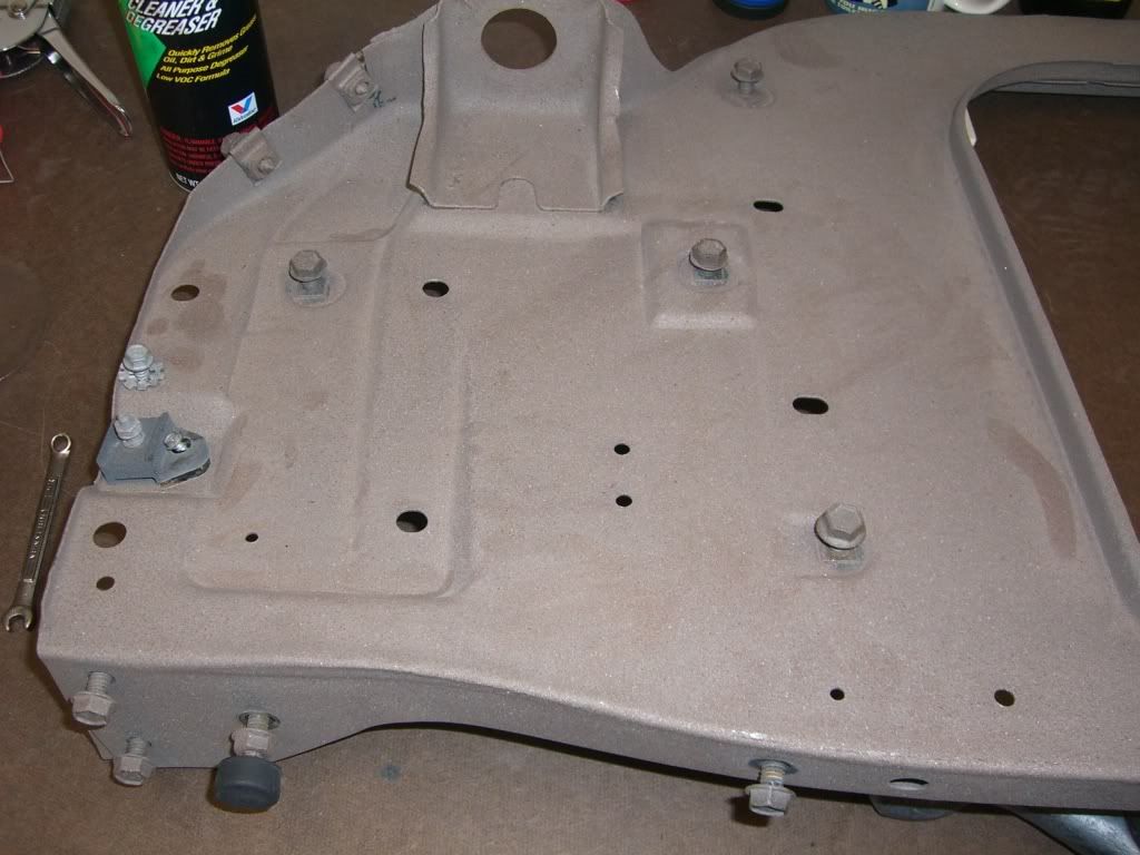
The next step is the installation of the Detroit Speed mini-tubs. These will allow as much as a 335 section tire, but I won't be going quite that wide. I'm only going to be able to fit a 275 up front and don't want a super wide disparity so I'll probably stick to a 315 or so out back. But I'll have room for more.
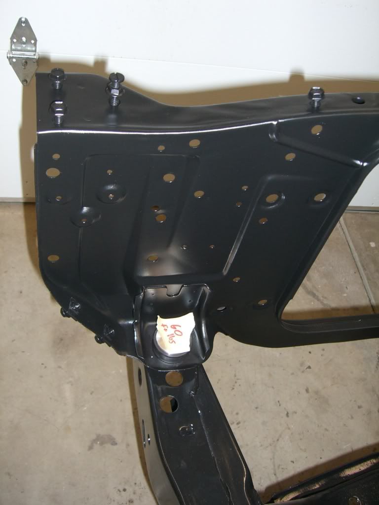
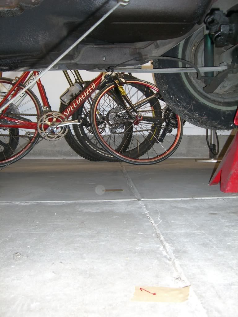
The first step of this process was to remove the rear suspension assembly. It came out absurdly easily. Seriously, I didn't even need to break out any penetrating oil or even so much as a breaker bar. Everything came apart with a 3/8" drive ratchet and minimal effort. God bless my grandparents for keeping this thing garaged for 35 years. It's spent more nights outside since Ive owned it (2000 on) than it has in it's entire live. The bolts looked literally brand new when I took them out.

The 4x4 patch of tape on the fender has marks on it identifying the axle centerline. This will be important for locating bits of the 3-link but more on that later.


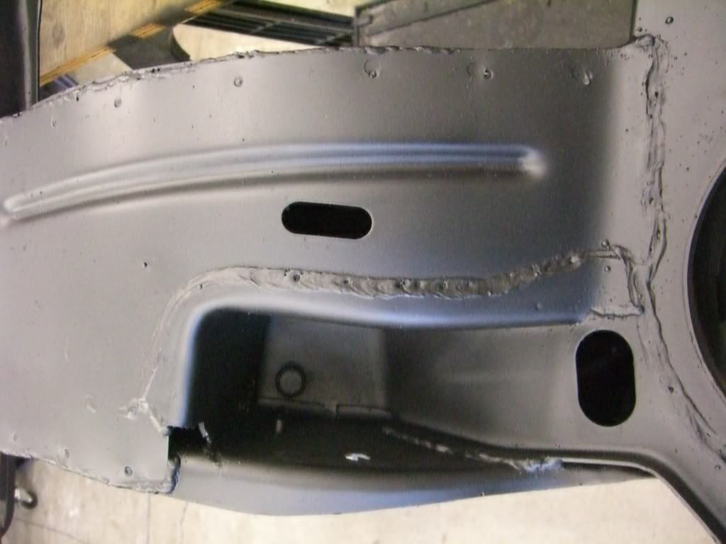
I'm not going to go into excruciating detail on the tub install. This thread outlines the process better than I ever could and it would be redundant to go over it in detail again.
http://www.pro-touring.com/forum/showthread.php?t=46900
I'll post a few photos here and there though.
Anybody need a complete rear suspension and 10-bolt rear for a 1968 Camaro? Free, if you come pick it up. Otherwise I'm tossing it.


 Brian Hobaugh SCCA National Tour June 2014
 First Hemi 'Cuda Convertible Ever Built
 Short clips: Goodguys Pleasanton autocross and pit videos


 Linear Mode

