...

Go Back   Lateral-g Forums > Lateral-G Open Discussions > Project Updates
User Name
Password


Reply
 
Thread Tools Display Modes
  #1  
Old 06-02-2008, 08:08 PM
sik68's Avatar
sik68 sik68 is offline
Senior Member
 
Join Date: Jul 2006
Location: San Francisco
Posts: 505
Thanks: 0
Thanked 0 Times in 0 Posts
Default

Awesome guys! Thanks for the support! Here's another update...
__________________
Steven

1968 Camaro: "TRACKDAY"

Build In Progress: https://lateral-g.net/forums/showthread.php4?t=10706
Reply With Quote
  #2  
Old 06-02-2008, 08:09 PM
sik68's Avatar
sik68 sik68 is offline
Senior Member
 
Join Date: Jul 2006
Location: San Francisco
Posts: 505
Thanks: 0
Thanked 0 Times in 0 Posts
Default

Tobin @ Kore3 has been awesome throughout this whole process. He informed me that the brake rotor hub requires that the axle flange be <=6". The flange of the original axles is much larger, requiring a turn-down or a replacment. I chose the latter, going with Superior Axles from Summit (SAG-EV10-1). The flange is 5.8" in diameter, so these axles work. They accept the standard 7/16" press in studs (included in box), as well as 1/2"-20 screw-studs (not included). I chose Moser 2" studs from Summit (MSR-8002). Here's a shot of the studs on the axle, along side the original axle.


I have the pictures of the axle overhaul on a different computer, so I will post a complete write-up on that soon.

Here's a picture of the driver's side axle installed, with the caliper bracket from Kore3. This bracket may look atypical to those who have seen the C5 brackets... that's because this bracket also accepts the in-rotor parking brake setup. Notice how the Global West 5 leaf springs aren't even captured by the monoleaf spring perches and a 1/2" lowering block? That's why I am going to order the DSE multileaf conversion kit.


Staggered Shocks: Notice the bracket is oriented at 9 o'clock. This is the correct position to avoid the shock on the driver's side, which goes behind the axle. On the passenger side of the vehicle, the bracket is also installed at 9 o'clock, to avoid the shock which goes in front of the axle. You must use 2 Left-Hand calipers with these staggered-shock cars so that the brakes can be bled properly.

I love tools. Installing the rear axles gave me an excuse to purchase a dial indicator. Here I am checking the runout


Results:
Driver's side: .003" total
Passenger side: .002" total

I'll do this once again with the rotors on the car...I will expect to see those runout numbers roughly multiplied by 2.
__________________
Steven

1968 Camaro: "TRACKDAY"

Build In Progress: https://lateral-g.net/forums/showthread.php4?t=10706
Reply With Quote
  #3  
Old 06-02-2008, 08:09 PM
sik68's Avatar
sik68 sik68 is offline
Senior Member
 
Join Date: Jul 2006
Location: San Francisco
Posts: 505
Thanks: 0
Thanked 0 Times in 0 Posts
Default

I am converting over to power steering with Unisteer's Gen II kit and the ATS/Lee 670 box. So I needed a solution for my pulley setup.

Here's my current setup, short water pump driving only the alternator


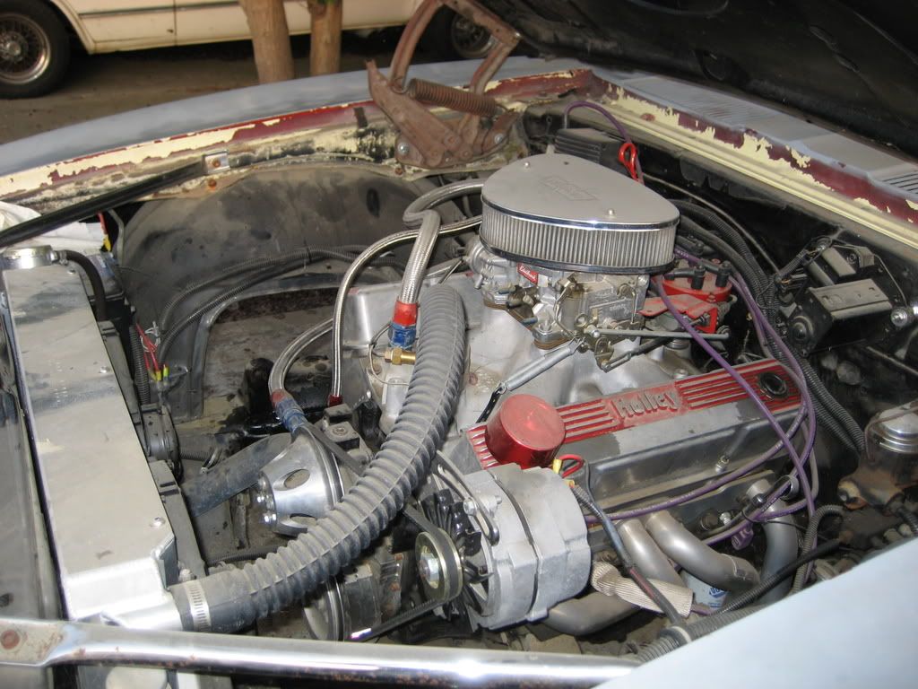
(BTW the Ron Davis Radiator you see is awesome)

What I needed was a alternator bracket that met several criteria:

1. Run everything from 1 belt
2. Keep the alternator on the driver side
3. NOT a header mount bracket, which I despise
4. Give enough room to allow clearance for the Gen II pump
5. Allow enough "bite" on the PS pump pulley

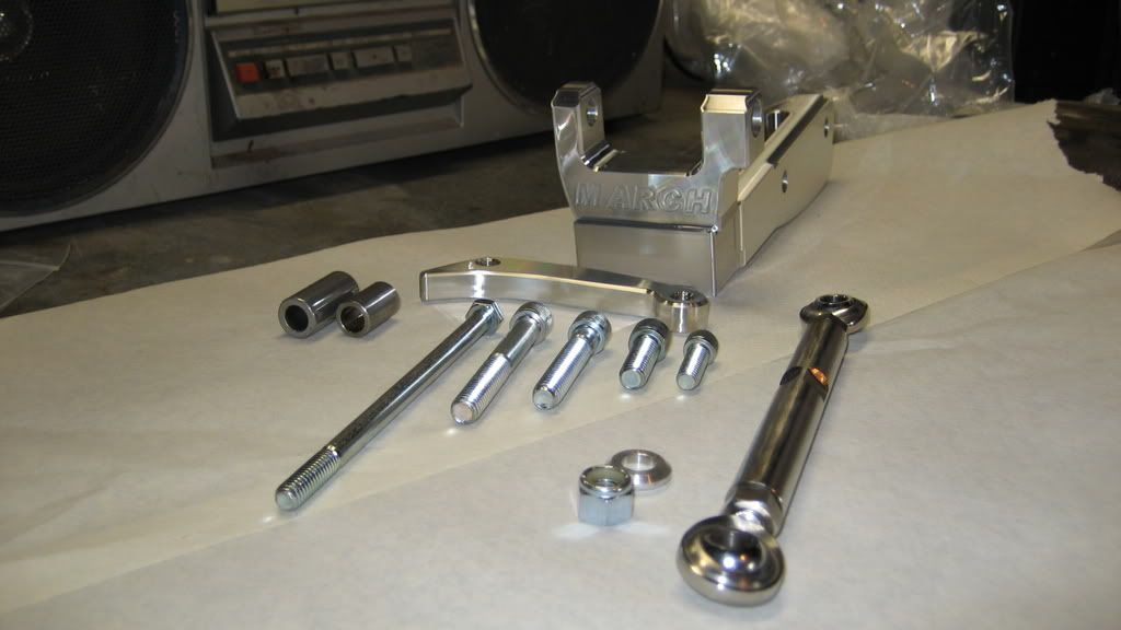
After much research, I was left with very few options. As I mentioned in my first post, I don't really go for the "bling parts." But I have to admit that I am pretty darn impressed with this alternator bracket I bought. It's a March product that I bought from Summit (MCH-20131). $160 dollars for a bracket isn't exactly my idea of a deal, but I really got what I paid for:


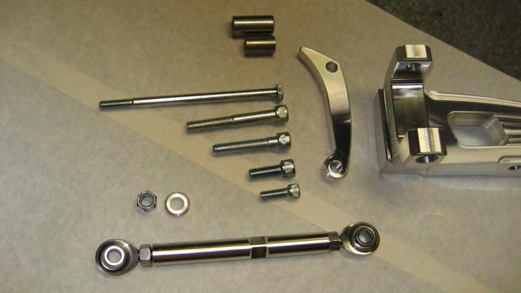
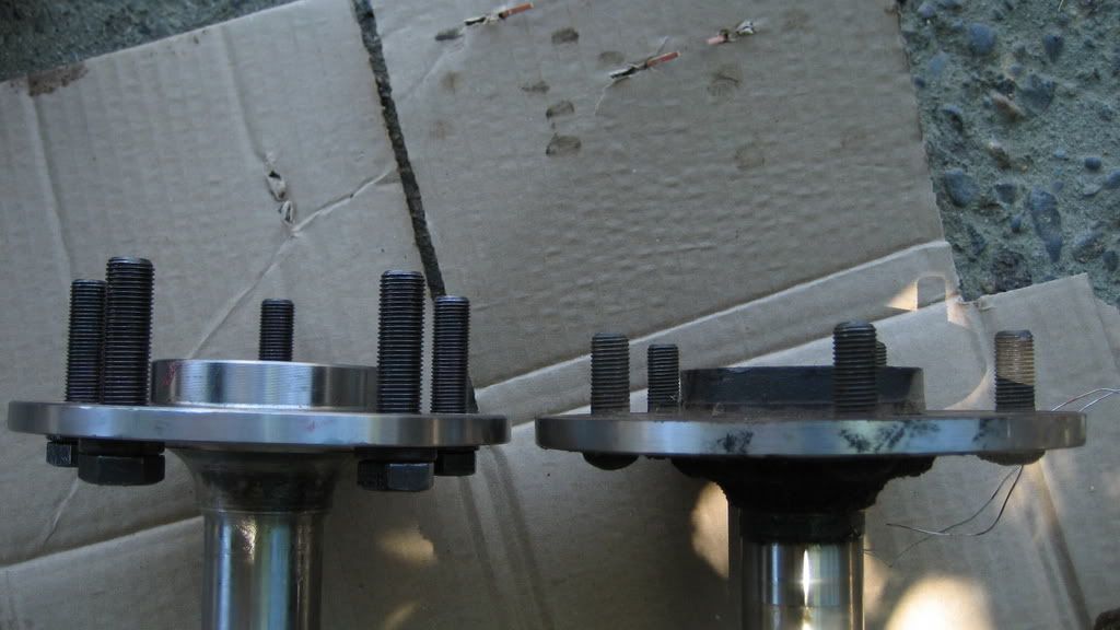
Note the longest bolt in the picture above, used to bolt the alternator up to the bracket. This is the 1/4" bolt that was included in the box, But it is is completely wrong...It should be 3/8" with an allen wrench head (Hex cap) just like every other bolt you see. I don't know how it got in there, but I had to run down to the hardware store to get the correct one.


Also, the shortest bolt you see wasn't correct for my application either! This is the bolt that is supposed to thread into the top hole of the alternator, holding the piece that the turnbuckle mounts to. The thread on the bolt is coarse, while the thread of the alternator is fine (or vice versa, I can't recall). I just simply reused the bolt I already had. These are the type of hangups that I have learned to accept very early in this project.

Here it is on the car:


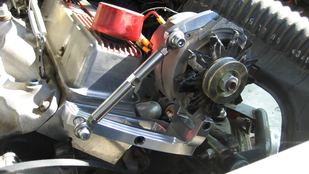
As you can see, it makes use of the 3/8" drilled accesory holes in the Pro-Topline heads, and provides awesome adjustability with the turnbuckle. It took several hours to install this bracket because I wanted to be sure that the bolts wouldn't bottom out when threading into the aluminum head. I actually bought a bolt that was a smidge shorter and touched it with a grinder, just to be sure. You can see the replacements (in black) HCS that I used to properly install the bracket and alternator. Mismatched bolts build character!

Whether it meets criteria 4 & 5 remains to be seen...I sure hope so.
__________________
Steven

1968 Camaro: "TRACKDAY"

Build In Progress: https://lateral-g.net/forums/showthread.php4?t=10706
Reply With Quote
  #4  
Old 06-11-2008, 11:28 PM
sik68's Avatar
sik68 sik68 is offline
Senior Member
 
Join Date: Jul 2006
Location: San Francisco
Posts: 505
Thanks: 0
Thanked 0 Times in 0 Posts
Default

Quick Update:

I spent some time preparing my C5 brake kit from Kore3. Here's a mock-up shot of the caliper on the ATS tall spindle:


I wanted the caliper abutment brackets to be a bit darker than stock, so I sprayed them with Dupont hi-temperature paint in matte black. The difference is subtle but it makes the red caliper "pop" quite a bit more. As shipped on left, painted on right:


Just for kicks, here is a mock-up I did a while back showing the rear abutment bracket:

__________________
Steven

1968 Camaro: "TRACKDAY"

Build In Progress: https://lateral-g.net/forums/showthread.php4?t=10706
Reply With Quote
  #5  
Old 06-12-2008, 04:14 AM
Steve Firebird's Avatar
Steve Firebird Steve Firebird is offline
Senior Member
 
Join Date: Feb 2006
Posts: 217
Thanks: 0
Thanked 0 Times in 0 Posts
Default

Good to see a few young guys really stepping up on these car builds. Looks like you have a good start on a wicked Camaro. I will be watching this thread. Steve
__________________
[SIGPIC][/SIGPIC]1968 Firebird AKA "Jinx" 455,TKO 600, Mini tubs,4 link and more...
1969 Firebird project "routy"
1997 TA sliver 6 speed with leather
Steve
Reply With Quote
  #6  
Old 06-12-2008, 09:12 AM
GHOSTDANCER GHOSTDANCER is offline
Senior Member
 
Join Date: Oct 2006
Location: Edwards CA
Posts: 714
Thanks: 0
Thanked 0 Times in 0 Posts
Default

Looking good
Reply With Quote
  #7  
Old 06-12-2008, 03:01 PM
sik68's Avatar
sik68 sik68 is offline
Senior Member
 
Join Date: Jul 2006
Location: San Francisco
Posts: 505
Thanks: 0
Thanked 0 Times in 0 Posts
Default

Thanks for the ongoing support!

As promised earlier, here's my write-up of my axle replacement. For 99% of you, swapping axles is a "been there, done that" excercise; but I'm writing it up to share my experiences for those that don't know what's up (like me when I unbolted the diff cover). I didn't get pictures of every step because I didn't feel like washing my hands so often to touch the camera. Luckily, my dad was standing by once in a while to get some shots.

First thing, get a Chilton's nice and greasy:


Next, grab a hold of the driveshaft and spin it until you see a bolt head such as this. This is the set pin which you will need to remove. Shown here:


Just 1 more step before the axles can be removed. Now that the pin is out, there is a steel "dowel" directly in the center of the differential that keeps the axles separate. Rotate the axle to a convienent position and then simply reach in there and push it in either direction. No need to remove it entirely...just far enough so the axles can slide inboard. Here's a pic:


After that, simply push the axles inboard to release the c-clips.

Ta-da!


Use a slide hammer (I rented from autozone) and the bearing puller attachment to get the seal and bearing out. Pay attention to which way the seal was facing, so that you install the new seal the same way (just in case).

It has been recommended to me over and over that you should always change out the bearings and seals whenever the axle is replaced. To install the new ones, you're going to have to get used to the painful feeling of beating on your car. My tension level skyrocketed during this part of the project, as I am a believer that a hammer is a substitution for using the correct tool. Anyways, I used a hammer and a socket to slowly tap around the outer race of the bearing until it "felt" seated against the lip of the axle housing. Then I did the same for the seal. I don't even like to talk about it that much, because the whole process just gave me the chills. "Just hammer until it feels right;" that's no way to build a car.

Anyways, it worked. NOTE: many have said that after you push the dowel out of position, don't rotate the assembly, as the differential components can fall out. If you need to change positions, push the pin back first.

To reinstall the axles, just do everything in reverse.

Update soon on the installation of the Gen 2 power steering pump from Unisteer.
__________________
Steven

1968 Camaro: "TRACKDAY"

Build In Progress: https://lateral-g.net/forums/showthread.php4?t=10706

Last edited by sik68; 06-12-2008 at 03:38 PM.
Reply With Quote
Reply


Posting Rules
You may not post new threads
You may not post replies
You may not post attachments
You may not edit your posts

BB code is On
Smilies are On
[IMG] code is On
HTML code is Off

Forum Jump


All times are GMT -7. The time now is 02:34 PM.


Powered by vBulletin® Version 3.8.11
Copyright ©2000 - 2025, vBulletin Solutions Inc.
Copyright Lateral-g.net