The trusty ol’ leaf spring. It’s been holding up vehicles from trucks, cars and even horse drawn wagons for over a hundred years. It’s one design that’s withstood the test of time and is still being used today.
The leaf spring is just about as simple as it can get in its design – a piece of metal that springs back into shape after you apply force to it. They can be stacked to be able to handle more weight, and can improve the ride quality. When it comes to suspension designs, they are tried and true and easy as pie to design. The flip side to their simplicity is their limit of performance. They can only get you so far, and then it’s time to step up.
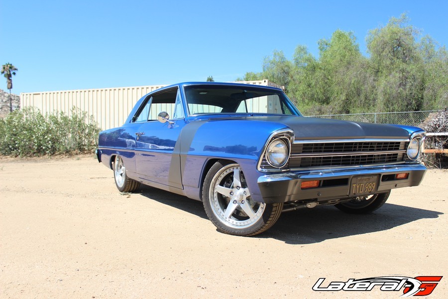
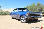
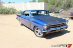
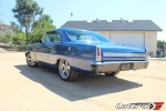
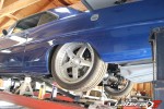
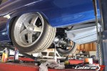
On our ’67 Nova we had reached that limitation. After swapping the front suspension on this car with updated tubular control arms, rack and pinion and coil overs, the car handled amazing. Going through corners the front of the car rode like it was on rails. But that’s when the next problem arose – the leaf springs in the rear. The rear end wasn’t keeping up to the task and the car felt like it was going to slide out from under us. We knew the next step was to ditch the leafs and swap to a four-link set up.
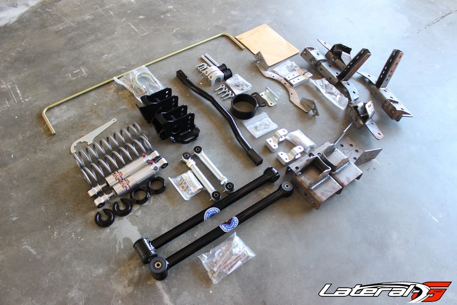
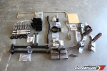
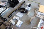
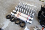
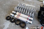
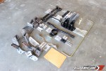
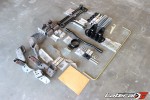
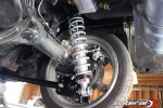
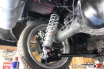
We wanted to see what our options are, so we started by hopping on the Chris Alston Chassisworks website. They had a ton of options from street, drag racing and pro-touring applications. We wanted the rear of this car to handle like the front. Right off the bat we noticed their Chevy II g-Bar system which converts our clunky leaf springs into a high performance four-link suspension system with VariShock coilovers and sway bar.
To find out a little more about the kit and all the options, we called Chris Alston Chassisworks and spoke with Lino Chestang about this kit. “The g-Bar coil-over system selected is part of a larger family of canted 4-link rear suspension systems that we offer for ’62-74 Novas, ’67-81 Camaros and Firebirds, and ’64-73 Mustangs and Cougars,” explained Chestang. “We offer three basic levels of performance, which include g-Bar systems with poly-bushed tubular steel lower links and billet uppers; g-Link systems with pivotball upper and lower links for increased performance; and billet g-Links that feature billet-aluminum lower links. Beyond that, customers can choose from multiple styles of swaybars, coil-over or air-spring VariShocks with various levels of valve adjustment, coil-spring rates, and whether to upgrade to one of our FAB9 Ford 9” conversion housings or use the existing factory rearend with bolt-on axle brackets. We can just as easily put together a system for a mild-budgeted street car or serious road racer,” continued Chestang. For our application, we went with reusing the factory 10-bolt rearend, along with their poly urethane bushing set-up.
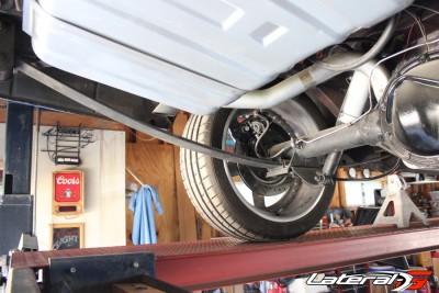
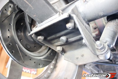
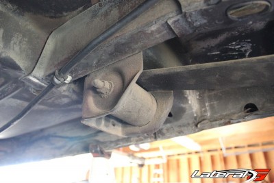
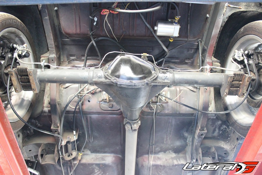
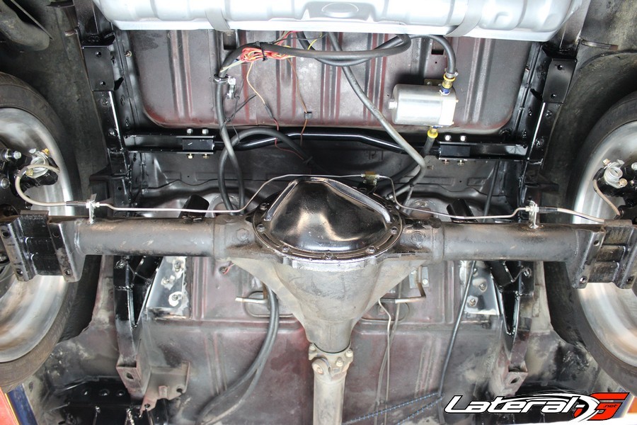
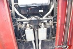
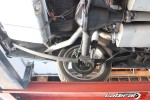
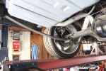
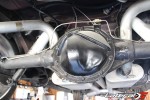
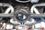
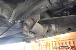
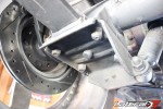
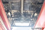
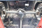
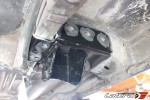
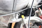
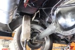
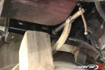
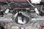
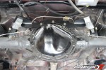
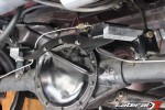
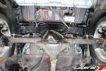
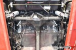
The first step of our installation was to get the car up on a lift and disconnect the battery. From here we started disassembling the rear suspension. With the car up on jack stands, we unbolted and removed both leaf springs. From there, we removed the entire exhaust system, as it would only be in our way throughout the entire installation. We also removed the emergency brake cables and tucked away some wiring.
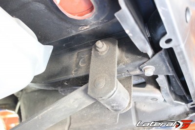
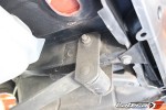
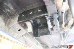
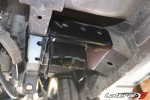
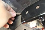
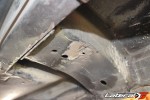
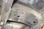
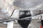
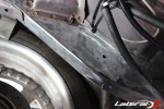
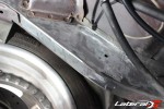
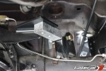
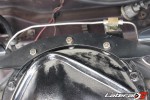
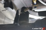
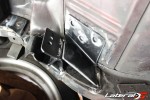
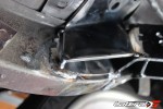
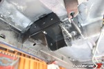
We decided to keep the rear end in the car during the installation, but we did have to remove the factory bolts that hold on the springs, and drill those holes out with a 1/2″ drill bit. The last step was to cut off the cages that held the front of the leaf springs on the body.
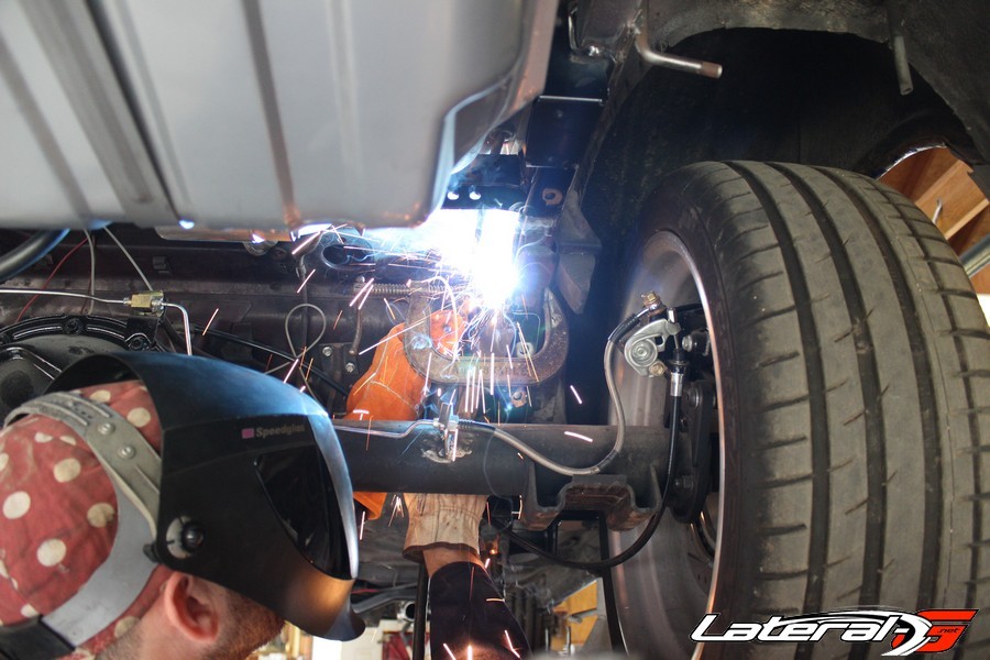
Weld ‘er up!
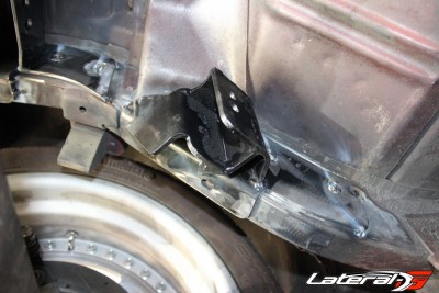
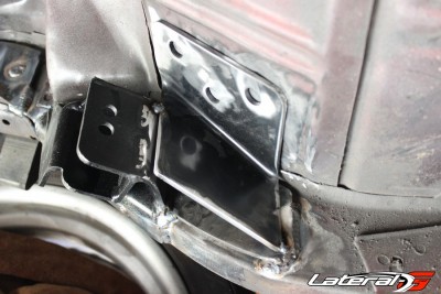
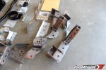
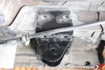
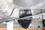
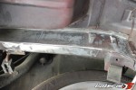
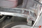
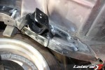
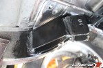
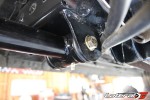
With all the old out of the way, we started in with the new. The first step was to install the two main frame brackets. These brackets not only strengthen the original frame rails, they also locate the upper control arms and sway bar mounts along with an additional support brace that goes right in front of the gas tank.
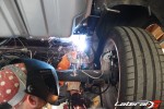
We made sure to take our time with these pieces, measuring over and over again to make sure they were square and in exactly the right place. Once we had the placement, we started the process of grinding all the surfaces where this kit needs to be welded up. Once that was done, we tacked welded these pieces in again, then measured again. Confident in our tape measure reading abilities, we welded up per the instructions, which includes stitch welding the entire bracket and welding up the holes.
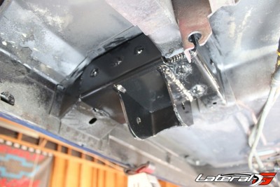
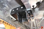
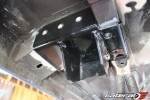
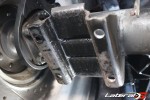
The next part to weld in was the new front lower control arm brackets. Since we already had removed the sheet metal cages that held the original leaf springs, these brackets just required us to slide them on. One thing we noticed is that they are a perfect fit, sliding on with no room for error and are a heck of a lot more beefy than the original spring mounts. The last step for these is to stitch weld them up and weld the holes up like on the frame brackets.
The last part to weld up is the brackets that attach the upper arms to the rearend housing. At first this seemed like a pretty intimidating task, with lots of room for error. However, Chris Alston Chassisworks made the process fool proof with a jig to put the brackets in the exact spot.
The first step was to grab the machined brackets that go onto the actual control arm brackets and bolt them to the jig. This jig then bolts to the rearend, using the rearend cover mounting bolt holes. In a matter of minutes, the upper control arm brackets were perfectly positioned on the rearend. A few welds and we were done with all the welding in the kit.
Bolting On The Goods
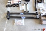
The hard part of the installation was done, we were able to put away the grinders and welder. After a quick coat of black spray paint, the time came to assemble the four link and sway bar. There’s a lot of parts to the installation, but with precise instructions and all the parts supplied including bolts, nuts and washers – it went pretty quick.
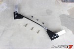
The first step we did was install the cross-over bar that goes from the two side rail brackets we welded earlier. Mind you, we had this in before fully welding to make sure it was square. Using four Grade 8 bolts, it was in its new home within a few minutes.
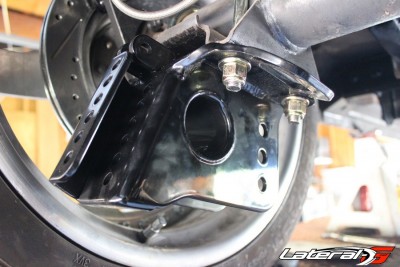
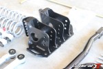
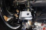
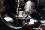
Once that was done, we continued by bolting on the lower control arm brackets to the rearend. Remember that during dis-assembly we had already drilled the mounting bolts out to 1/2″ holes. From here we used the supplied U-Bolts, and tightened down the new bracket to the rearend. The lower brackets have a number of features for added functionality. The rear of the bracket will be home to the billet lower shock mounts with multiple holes for easy ride height adjustments. Three holes along the front of the bracket are for the adjustment of the lower control arm position to adjust suspension geometry. A tie-down loop has also been added to make securing to a trailer a bit easier for us.
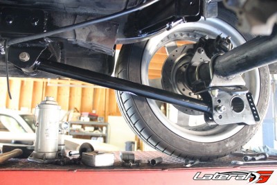
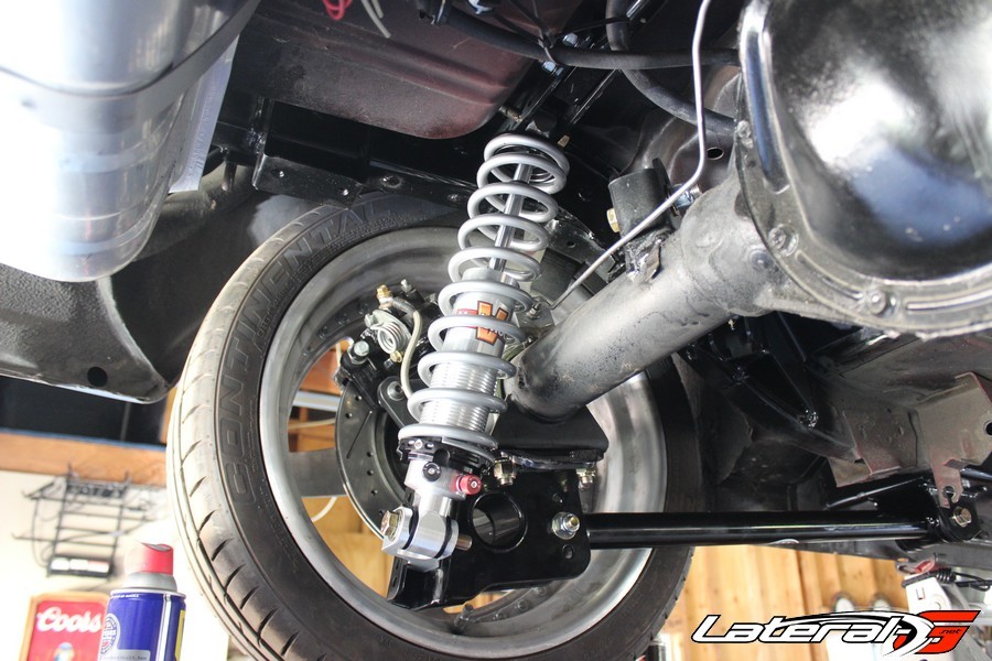
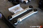
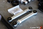
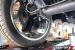
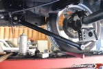
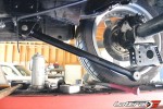
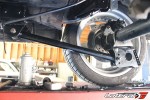
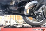
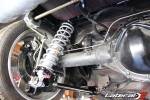
Starting with the lower control arms, we slid them into place. They are a tight fit as they are precisely made along with the brackets. Using the supplied Grade 8 bolts, we now had the lowers installed. The uppers went in the same way, tight and secure. On all four arms make sure to orientate them so the grease zerks are pointing down on the lower arms, and away from the brackets on the uppers so you can access them. Suspension geometry adjustments can also be made at the upper control arms by moving the chassis and housing mounting position up or down. It is initially set at the top chassis hole and lower housing hole. After testing if the car needs a little more bite for better acceleration, the arms can be moved to the other holes.
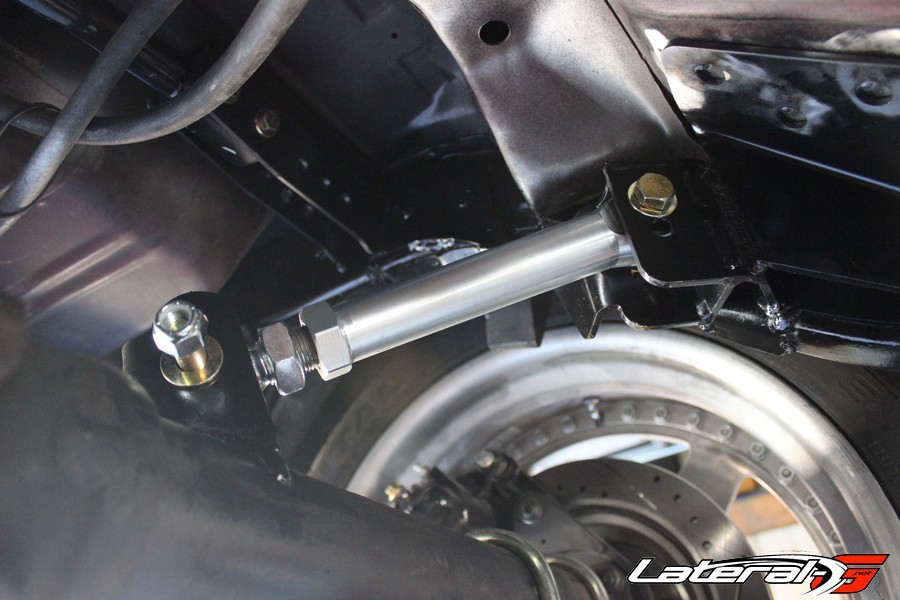
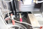
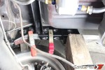
Upper control arms installed. Note: Bracket that welds to the floor in right of picture was fully welded later once the rear seat was removed.
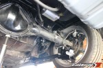
With all four arms in place, we took time to articulate the suspension and check for binding and clearance issues. While they are large wheels on the back, they aren’t the biggest we could fit so we had plenty of room when lifting the axle up and down through its range of motion. During this time we also checked for clearances side to side to make sure the rearend was square under the car. We did have to make some minor adjustments to get things perfect, which involved unbolting the arm from one end to adjust its length.
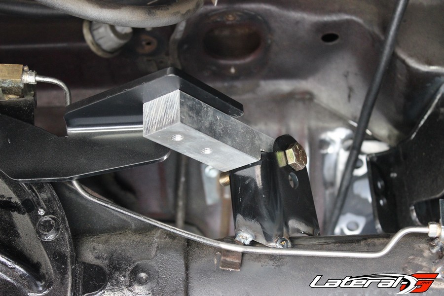
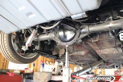
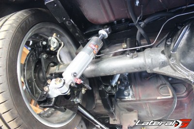
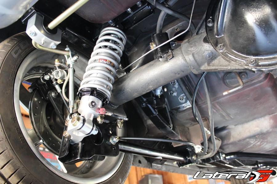
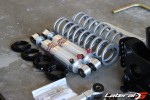
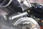
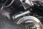
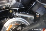
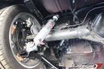
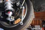
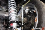
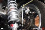
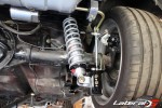
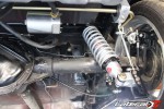
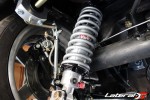
At this point we started on installing the VariShock coil-overs. These are dual-adjustable, along with being able to compress the springs and move their mounting points to adjust ride height. Starting with the machined aluminum bracket, we bolted it to the rearend bracket. The upper end of the coil over went in the welded in frame brackets. The upper brackets have three mounting positions to change the shock angle. This is useful for adjusting the overall stiffness of the spring and shock, innermost hole being softer and outer hole stiffer, or to simply gain a little more room for exhaust routing.
With the coil-overs installed, we took some time to set the weight of the car on the rear suspension. With our set up, the rear of the car sat way too low. We re-positioned the coil overs and tightened up the springs a bit. We also knew that there will be some settling after driving the car around for a few miles. With all the different adjustments available, there’s no problem getting the ride height and performance dialed on this kit.
Now that the car was at ride height, we wanted to get the pinion angle dialed in. Using a dial, we adjusted the upper control arms to get the proper pinion angle. Pinion angle set, we moved onto the sway bar.
Sway-Bar Install
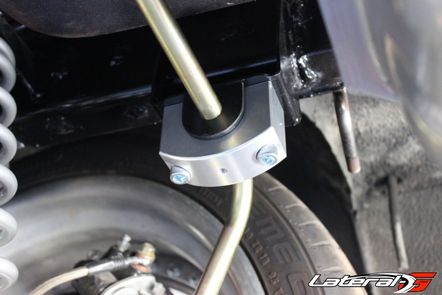
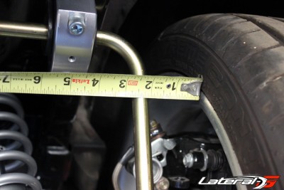
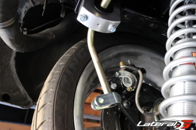
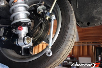
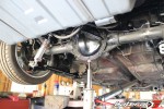
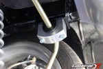
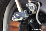
The first step installing the sway bar is to take a tap and clean out the threads. Grabbing the poly bushings, we slide those onto the bar and into the machined brackets. We left the bolts loose, so we could make sure the sway bar was perfectly centered under the car. The last step was to install the end links, and tighten down the brackets. The billet clevis can also be moved to one of three positions along the swaybar arm to change its stiffness. We’ll start at the softest setting before road testing.
At this point we reassembled the emergency brake cables and the few other items we moved during dis-assembly. Then we went over the entire rear suspension with the weight of the car on it, tightening all the bolts down to the correct torque specs and hitting all the grease zerks along the way.
Racing a car is one way to find the weakest link. After completing the front suspension install and now the rear suspension install, we already knew what the next link would be – the unibody. These early Nova’s and first gen Camaro’s were all uni-body cars that flex like a tree branch in a storm. Before even testing out the new rear suspension, we ordered up a Chris Alston Chassisworks sub-frame connectors. Check out the gallery of pictures below!.
Chris Alston Chassisworks Website, Phone: (888) 388-0297, Click here for full installation instructions
- Out with the old, time for the new!


